
Page 312 - Peter Paul 2019 Catalog
P. 312
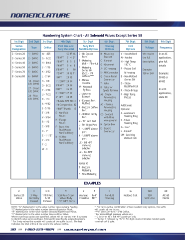
 NOMENCLATURE
   Numbering System Chart - All Solenoid Valves Except Series 58
  1st Digit
    2nd Digit
   3rd Digit
  4th Digit
   5th Digit
    6th Digit
  7th Digit
    8th Digit
   9th Digit
  Series Designation
   Type
  Orifice
 Port Size and Body Material
  Body Port Function Options
   Housing Options
 Coil Options
   Voltage
  Frequency
  2 - Series 20 3 - Series 30 4 - Series 40 5 - Series 50 7 - Series 70 8 - Series 80
   1-2WNO
2-2WNC
3-3WNC
4-3WNO
5-3WDC
6-3WMP
18 - Direct Lift 2WNO
27 - Direct Lift 2WNC
28 - Pilot Lift 2WNC
  M-.025 G-1/32 H-3/64 J-1/16 K-3/32 L - 7/64 N-1/8 O-5/32 P-3/16 U-7/32 R-1/4
A - 9/32 S-5/16 T-3/8 V-5/64 B-1/2 C-5/8 D-1” E-11/2” Y-3/4 F-2 W-3
 1/8NPT 1/8NPT 1/4NPT 3/8 NPT 1/2 NPT 1 NPT
1 1/2 NPT 3/4NPT 2 NPT
SS BR AL 742††
8 5 2 9 6 3 1 10 33 12 11
23 13 24 14 2919 26 16 27 17 28 18
2 1/2 NPT
3” NPT
1/8 Male NPT BR 31
1/4Compression
1/8 NPT Plastic
E - Manifold Mount
H - Flange Mount
F - Brass Hex Stud Mount
Manifold Body
N-SSHex Stud Mount
Manifold Body
32 15
  D - No Option Ports
T - Metering
(1/8 - 1/8 orif.)
F - Metering Series 70
(5/32 - 1/4 orifice) ****
Y - Manual Override
W - Metered By-Pass
U - Metered Exhaust
V - Exhaust Port Muffled
R - Bottom Orifice Port
O - Bottom cavity Port
M - 90° Left Port
L - 90° Right Port
Z - 1/4 NPT sleeve port
X - 1/8 NPT sleeve port
UX - 1/8 NPT metered
adapter
UZ - 1/4 NPT metered
adapter
Series 50
T - Bottom Metering
F - Side Metering
   B - Mounting Bracket
C - Conduit
G - Grommet
J - JIC Housing
S - AN Connector
Q - Strain Relief Connector
Y-Yoke
K-Yokefor Spade Terminal
AS - Single Automotive
Housing
AD - Double Automotive
Housing
CC- Conduit with third
wire ground
N - Splice Box
E - Export Connecter
 V - Non Molded
M - Molded
H - High Temp. 180°C
P - Potted Coil & Housing
B - Non Molded (Series 50)
D - Diode Rectified Coil
R - Diode Bridge
F - High Temp. Potted
Additional
Options:
A - Aluminum Shading Ring
S - Silver Shading Ring
G-Gas†
L - Liquid †
LM - Latching Molded Coil
   We require the full description.
Example: 120 or 240
  In an AC application, give full details
Example: 50HZor 60 HZ
InaDC application, state DC
   EXAMPLES
 2
Series 20 Valve
    3
3-Way Normally Closed
   NK
1/8 Inlet 3/32 Exhaust
  9
Stainless Steel Valve Body 1/4” NPT Ports
   YZ
Manual 1/4” Override NPT
    C
Conduit Housing
  M Molded Coil
    120
120 Volt Line
   60
AC 60 Hertz
 NOTE: “G” Marked prior to the valve number denotes Gang Feeding. “E” Marked prior to the valve number denotes Explosion Proof.
“H” Marked prior to the valve number denotes High Pressure Valve. “F” Marked prior to the valve number denotes Filter Valve.
Where numerous options are specified, valves will be marked with 2 numbers to identify valve series and type, followed by specifically assigned numbers. * For 3 way valves this number will consist of two suffix letters. The first indicates the inlet orifice & the second the exhaust orifice.
** For valves with a combination of two standard body options, this suffix will consist of two letters.
**** In Series 70 -1/16 - 5/16 Orifice.
† For series H high pressure valves only.
†† 2 in Series 15 is 1/8 NPT Aluminum only.
††† Letter K followed by “M” in 7th digit column indicates molded spade terminal coil & yoke.
310 >>> 1-860-229-4884 >>> www.peterpaul.com
