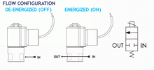
Peter Paul Excellence

Series 20 Model E22

Hazardous Location
2-Way Normally Closed Valve

Peter Paul explosion proof valves are used where fire or explosion hazards exist due to the presence of flammable gases or vapors, flammable liquids, combustible dust, or easily ignitable fibers. Hazardous Location valves are recommended, or in some cases compulsory, where a high level of protection from explosion is required.

• Explosion Proof
• The flagship valve initially created for fluid power industry.
• Heavy duty and made of stainless steel.
• A real workhorse with proven performance.
• It has the greatest amount of options available of all the valves.
• Wide range of orifice sizes from 1/32″ to 1/4″.

  • SPECIFICATIONS
  • 2-D & 3-D CAD DRAWING
  • FLOW CHART
  • NOMENCLATURE
VALVE SPECIFICATIONS

+ MAX. OPER.
PRESS. DIFF.
ORIFICE SIZE CV FACTOR     VALVE NUMBER  
AC DC         1/8 NPT PORTS 1/4 NPT PORTS  
500   500   1/32 .024     E22G7DCCM E22G9DCCM    
250 (500) 250 (500) 3/64 .052     E22H7DCCM E22H9DCCM    
200 (400) 200 (400) 1/16 .095     E22J7DCCM E22J9DCCM    
125 (300) 125 (250) 3/32 .156     E22K7DCCM E22K9DCCM    
100 (200) 100 (200) 1/8 .284     E22N7DCCM E22N9DCCM    
75   50   5/32 .404     E22O7DCCM E22O9DCCM    
50   25   3/16 .500     E22P7DCCM E22P9DCCM    
20   5   1/4 .700     E22R7DCCM E22R9DCCM    

WHEN ORDERING VALVES OR REPAIR KITS ADD VOLTAGE AND FREQUENCY TO COMPLETE
VALVE NUMBER. EXAMPLES: VALVE (E22N9DCCM-120/60) REPAIR KIT (2KE22K-AC)

+ Ratings in brackets are optional extended ratings; consult factory.

OPERATING CONDITIONS

Media: Air, water, and other fluids compatible with standard Buna seals. Hot water, steam gasoline, and many oils require special seal materials. (Series 20 pressure ratings may change due to the viscosity of the liquid.)*
Valve Temperature Range: Standard Valves – 0°F (-18°C) to 104°F (40°C) ambient; 0°F (-18°C) to 150°F (65°C) media. Optional Valves – can tolerate much higher or much lower ambient and media temperatures.*
Maximum Operating Pressure Differentials: See table above.
Burst Pressure: 5000 PSI
Leakage: Bubble tight for standard valves.
Vacuum: To 5 Microns*

ELECTRICAL CHARACTERISTICS

Coil Voltage: 6 to 825V AC 60 HZ. and 5 to 720V AC 50 HZ. — 1.8 to 265V DC
Nominal Power: AC — 7.3 Watts DC — 9.5 Watts
Coil Construction: Molded Class F with third wire ground (Std.), Class H or Potted (Opt.)
Typical Response Time on Air: 4 – 16 Milliseconds
Operating Speed: Up to 600 CPM
Duty Cycle: Continuous

MECHANICAL CHARACTERISTICS

Body: Stainless Steel (Std.) or Brass (Opt.)
Internal Components: Stainless Steel
Elastomers: Nitrile (Buna) (Std.). Many other elastomers available.*
Orifice Diameter: See table above.
Porting: See table above.
Housing: Flame-Proof construction with 1/2″ NPT conduit
Listings: Valves are UL listed and certified for Hazard Locations — Class I, Div 1, Group C and D – Class II, Div 1, Group E, F, and G; Div 2, Groups C, D, E, F, and G.
Life Expectancy: Millions of cycles, depending on application, lubrication, etc.
Valve Weight: 1.38 lbs
Repair Kits: See table above.
Options: Alternate Port Locations, Metering, Manual Override, Alternate Elastomers*

* Consult representative or factory for options and specifications.

Series 20 Hazardous Location Valves

  A A1 A2 A3 A4 A5 B C C1 C2 C3 C4
 
inches 2.75 3.48 2.92 3.65 3.22 3.95 .34 1.67 2.39 2.15 1.65 2.63
mm 69.9 88.4 74.1 92.6 81.8 100.3 8.6 42.5 60.7 54.7 42.0 66.8
 
  D D1 D2 E F G H I I1 J J1 K
 
inches 1.69 1.61 1.88 .88 .88 #10-32 X .31 1/8 OR 1/4 NPT 1.88 2.13 .92 .85 2.52
mm 42.9 41.0 47.7 22.4 22.4 7.9 DP 1/8 OR 1/4 NPT 47.8 54.1 23.4 21.5 64.0
 

Numbering System Chart

Series Designation

Type

Orifice*

Port Size And Body Material

Body Port and Function Options

Housing Options

Coil Options

Voltage

Frequency

NOTE: “G” Marked prior to the valve number denotes Gang Feeding.
“E” Marked prior to the valve number denotes Explosion Proof.
“H” Marked prior to the valve number denotes High Pressure Valve. “F” Marked prior to the valve number denotes Filter Valve.
Where numerous options are specified, valves will be marked with 2 numbers to identify valve series and type, followed by specifically assigned numbers.
* For 3 way valves this number will consist of two suffix letters. The first indicates the inlet orifice & the second the exhaust orifice. ** For valves with a combination of two standard body options, this suffix will consist of two letters.
**** In Series 70 -1/16 - 5/16 Orifice.
† For series H high pressure valves only.
†† 2 in Series 15 is 1/8 NPT Aluminum only.
††† Letter K followed by “M” in 7th digit column indicates molded spade terminal coil & yoke.
SPECIFICATIONS ARE SUBJECT TO CHANGE WITHOUT NOTICE.