Peter Paul Excellence

Series 20 Model EH21
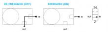
Hazardous Location High Pressure
2-Way Normally Open Valve

This valve uses the same kinetic energy impact mechanism as the EH22 but incorporates an internal rocker arm to reverse the action of the sealing pin. The kinetic energy of the plunger is applied to one end of the rocker arm when the coil is de-energized. This lifts the sealing pin, on the opposite end of the rocker arm, against the force of high pressure. A return spring acts directly on the pin, sealing the orifice when the coil is energized. For use on Air and other non-corrosive gasses, water and oil.

• Precision stainless steel rocker arm.
• Kel-F pin sealing element.
• Orifice guides the sealing pin for near perfect alignment.
• Simple construction…only three moving parts.
• Explosion proof construction.

  • SPECIFICATIONS
  • 2-D & 3-D CAD DRAWING
  • FLOW CHART
  • NOMENCLATURE

VALVE SPECIFICATIONS

MAX. OPER.
PRESS. DIFF.
ORIFICE SIZE CV FACTOR     VALVE NUMBER
CONDUIT HOUSING
 
GAS LIQUID         GAS LIQUID  
3000 3000 1/32 .024     EH21G7DCCM EH21G7DCCM    
2500 1500 3/64 .052     EH21H7DCCMG EH21H7DCCML    
1350 850 1/16 .095     EH21J7DCCMG EH21J7DCCML    
450 300 3/32 .156     EH21K7DCCMG EH21K7DCCML    

WHEN ORDERING VALVES OR REPAIR KITS ADD VOLTAGE AND FREQUENCY TO COMPLETE
VALVE NUMBER. EXAMPLES: VALVE (EH21J7DCCMG 120/60) REPAIR KIT (2KEH21J-AC)

OPERATING CONDITIONS

Media: Air and other non-corrosive gasses, water and oil.
Filtration: Down to 60 microns or less is recommended.
Valve Temperature Range: Standard Valves – 0°F (-18°C) to 104°F (40°C) ambient; 0°F (-18°C) to 150°F (65°C) media. Optional Valves – can tolerate much higher or much lower ambient and media temperatures.*
Maximum Operating Pressure Differentials: See table above.
Burst Pressure: 10,000 PSI
Leakage: Bubble tight

ELECTRICAL CHARACTERISTICS

Coil Voltage: 6 to 825V AC 60 HZ. and 5 to 720V AC 50 HZ.— 1.8 to 265V DC
Nominal Power: AC — 7.3 Watts DC — 9.5 Watts
Coil Construction: Molded Class F with third wire ground (Std.), Class H or Potted (Opt.)
Typical Response Time on Air: 4 – 16 Milliseconds
Operating Speed: Up to 600 CPM with gas media
Duty Cycle: Continuous

MECHANICAL CHARACTERISTICS

Body: 300 Series Stainless Steel
Internal Components: Stainless Steel
Elastomers: Nitrile (Buna) (Std.). Many other elastomers available.*
Sealing Pin: Kel-F (Std.), Delrin®, Teflon®, Nylon, PEEK, Radel®, Ultem®, 303 Stainless Steel (Opt.)
Orifice Diameter: See table above.
Porting: 1/8″ NPT
Housing: Flame-Proof Construction with 1/2″ NPT conduit
Mounting: Must be mounted within 30° of vertical.
Listings: Valves are UL listed and certified for Hazard Locations — Class I, Div 1, Group C and D – Class II, Div 1, Group E, F, and G; Div 2, Groups C, D, E, F, and G.
Life Expectancy: Millions of cycles, depending on application, lubrication, etc.
Valve Weight: 2.38 lbs
Repair Kits: See table above.
Options: Alternate Sealing Pin Materials and Alternate Elastomers*

* Consult representative or factory for options and specifications.

Series 20 High Pressure Valves

  A A1 A2 A3 A4 A5 B C C1 C2 C3 C4
 
inches 2.75 3.48 2.92 3.65 3.22 3.95 .34 1.67 2.39 2.15 1.65 2.63
mm 69.9 88.4 74.1 92.6 81.8 100.3 8.6 42.5 60.7 54.7 42.0 66.8
 
  D D1 D2 E F G H I I1 J J1 K
 
inches 1.69 1.61 1.88 .88 .88 #10-32 X .31 1/8 OR 1/4 NPT 1.88 2.13 .92 .85 2.52
mm 42.9 41.0 47.7 22.4 22.4 7.9 DP 1/8 OR 1/4 NPT 47.8 54.1 23.4 21.5 64.0
 

Numbering System Chart

Series Designation

Type

Orifice*

Port Size And Body Material

Body Port and Function Options

Housing Options

Coil Options

Voltage

Frequency

NOTE: “G” Marked prior to the valve number denotes Gang Feeding.
“E” Marked prior to the valve number denotes Explosion Proof.
“H” Marked prior to the valve number denotes High Pressure Valve. “F” Marked prior to the valve number denotes Filter Valve.
Where numerous options are specified, valves will be marked with 2 numbers to identify valve series and type, followed by specifically assigned numbers.
* For 3 way valves this number will consist of two suffix letters. The first indicates the inlet orifice & the second the exhaust orifice. ** For valves with a combination of two standard body options, this suffix will consist of two letters.
**** In Series 70 -1/16 - 5/16 Orifice.
† For series H high pressure valves only.
†† 2 in Series 15 is 1/8 NPT Aluminum only.
††† Letter K followed by “M” in 7th digit column indicates molded spade terminal coil & yoke.
SPECIFICATIONS ARE SUBJECT TO CHANGE WITHOUT NOTICE.