Peter Paul Excellence

Series 20 Model EH23

Hazardous Location High Pressure
3-Way Normally Closed Valve (exhaust to atmosphere)

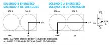
A complete line of valves with a great selection of options and exceptional proven performance. Using the heart of the highly successful model H22, Peter Paul Electronics has a dual operator valve that allows the same media control as a three way normally closed valve but at much higher pressure ratings than previously available. To function as a 3-way normally closed valve, operators must be alternately energized and de-energized. Pressure applied to the “IN” port must always be equal to or greater than the pressure in “CYL” port. Air and other non-corrosive gasses, water and oil.

• Made for higher pressure ratings.
• Precision stainless steel, free floating plunger.
• Kel-F pin sealing element.
• Orifice guides the sealing pin for near perfect alignment.
• Simple construction…only two moving parts.
• Explosion proof construction.

  • SPECIFICATIONS
  • 2-D & 3-D CAD DRAWING
  • FLOW CHART
  • NOMENCLATURE

VALVE SPECIFICATIONS

GAS PRESSURE RATINGS ORIFICE SIZE CV FACTOR VALVE NUMBER
AC DC 1/4 NPT PORTS
3000 3000 1/32 .022 EH23GG19DCCM
2500 1500 3/64 .041 EH23HH19DCCMG
1750 500 1/16 .065 EH23JJ19DCCMG
650 100 3/32 .100 EH23KK19DCCMG
LIQUID PRESSURE RATINGS ORIFICE SIZE CV FACTOR VALVE NUMBER
AC DC 1/4 NPT PORTS
3000 3000 1/32 .022 EH23GG19DCCM
1500 1500 3/64 .041 EH23HH19DCCML
1000 500 1/16 .065 EH23JJ19DCCML
300 100 3/32 .100 EH23KK19DCCML

WHEN ORDERING VALVES OR REPAIR KITS ADD VOLTAGE AND FREQUENCY TO COMPLETE
VALVE NUMBER. EXAMPLES: VALVE (EH23JJ19DCCML-120/60) REPAIR KIT (2KEH23JJ-AC)

OPERATING CONDITIONS

Media: Air and other non-corrosive gasses, water and oil.
Filtration: Down to 60 microns or less is recommended.
Valve Temperature Range: Standard Valves – 0°F (-18°C) to a maximum of 221°F (105°C) including coil heat rise, ambient and media temperatures. Other temperature ranges available on request — along with specific application parameter information specified.*
Maximum Operating Pressure Differentials: See table above.
Burst Pressure: 10,000 PSI
Leakage: Bubbletight (with polymer sealing pins)

ELECTRICAL CHARACTERISTICS

Coil Voltage: 6 to 825V AC 60 HZ. and 5 to 720V AC 50 HZ.— 1.8 to 265V DC
Nominal Power: AC — 7.3 Watts DC — 9.5 Watts (Per Operator)
Coil Construction: Molded Class F with third wire ground (Std.), Class H or Potted (Opt.)
Typical Response Time on Air: 4 – 16 Milliseconds
Operating Speed: Up to 600 CPM with gas media
Duty Cycle: Continuous

MECHANICAL CHARACTERISTICS

Body: 300 Series Stainless Steel
Internal Components: Stainless Steel
Elastomers: Nitrile (Buna) (Std.). Many other elastomers available.*
Sealing Pin: Kel-F (Std.), Delrin®, Teflon®, Nylon, PEEK, Radel®, Ultem®, 303 Stainless Steel (Opt.)
Orifice Diameter: See table above.
Porting: 1/4″ NPT
Housing: Flame-Proof Construction with 1/2″ NPT conduit
Mounting: Must be mounted within 30° of vertical.
Listings: Valves are UL listed and certified for Hazard Locations — Class I, Div 1, Group C and D – Class II, Div 1, Group E, F, and G; Div 2, Groups C, D, E, F, and G.
Life Expectancy: Millions of cycles, depending on application, lubrication, etc.
Valve Weight: 3.63 lbs
Repair Kits: See table above.
Options: Alternate Sealing Pin Materials and Alternate Elastomers*

* Consult representative or factory for options and specifications.

Series 20 Model EH23

A B C D E F G H I J
inches 3.42 3.25 1.88 3.81 1.50 2.00 2.33 1.25 .44 2.00
mm 86.9 82.9 47.8 96.8 38.1 50.8 59.2 31.8 11.2 50.8
K L M N P R S T U
inches 1.19 1.66 1/2 NPT CONDUIT 1/4 NPT .20 .36 .75 .72 .66
mm 30.2 42.2 5.1 9.1 19.1 18.3 16.8

Numbering System Chart

Series Designation

Type

Orifice*

Port Size And Body Material

Body Port and Function Options

Housing Options

Coil Options

Voltage

Frequency

NOTE: “G” Marked prior to the valve number denotes Gang Feeding.
“E” Marked prior to the valve number denotes Explosion Proof.
“H” Marked prior to the valve number denotes High Pressure Valve. “F” Marked prior to the valve number denotes Filter Valve.
Where numerous options are specified, valves will be marked with 2 numbers to identify valve series and type, followed by specifically assigned numbers.
* For 3 way valves this number will consist of two suffix letters. The first indicates the inlet orifice & the second the exhaust orifice. ** For valves with a combination of two standard body options, this suffix will consist of two letters.
**** In Series 70 -1/16 - 5/16 Orifice.
† For series H high pressure valves only.
†† 2 in Series 15 is 1/8 NPT Aluminum only.
††† Letter K followed by “M” in 7th digit column indicates molded spade terminal coil & yoke.
SPECIFICATIONS ARE SUBJECT TO CHANGE WITHOUT NOTICE.