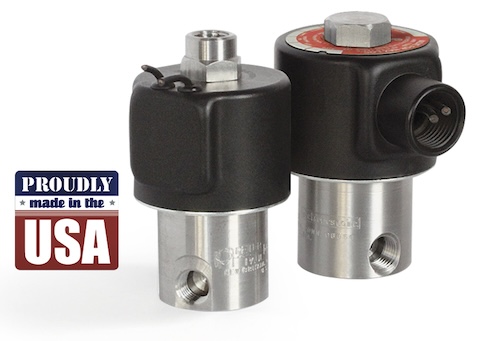
Peter Paul Excellence

Series 15 Model 153

3-Way Normally Closed Valve (piped exhaust)

The little black box — magnetic components encased in epoxy for durability and reliability. Interior parts are stainless steel and anodized aluminum. The valves may be used with air, inert gas and liquid media at pressures from vacuum to 200 psi — depending upon orifice size and configuration. For those who require extra heat resistance and media compatibility FKM and other elastomers are available.

• Small, lightweight and economical.
• Operating pressures from vacuum to 200 psi.
• Quality design and construction.

  • SPECIFICATIONS
  • 2-D & 3-D CAD DRAWING
  • FLOW CHART
  • NOMENCLATURE
VALVE SPECIFICATIONS

MAX. OPER.
PRESS. DIFF.
ORIFICE SIZE CV FACTOR VALVE NUMBER
AC DC NC NO NC NO LEAD WIRE UNIT EUROPEAN DIN CONDUIT HOUSING
200 200 1/32 1/32 .022 .020 153GG2XGM 153GG2XEM 153GG2XCM
150 150 3/64 3/64 .055 .048 153HH2XGM 153HH2XEM 153HH2XCM
150 150 3/64 1/16 .055 .075 153HJ2XGM 153HJ2XEM 153HJ2XCM
100 100 1/16 1/16 .075 .075 153JJ2XGM 153JJ2XEM 153JJ2XCM
60 60 3/32 1/16 .130 .075 153KJ2XGM 153KJ2XEM 153KJ2XCM
50 50 3/32 3/32 .130 .130 153KK2XGM 153KK2XEM 153KK2XCM

WHEN ORDERING VALVES OR REPAIR PACKS ADD VOLTAGE AND FREQUENCY TO COMPLETE
VALVE NUMBER. EXAMPLES: VALVE (153JJ2XGM-120/60) REPAIR PACK (K153JX-AC)

OPERATING CONDITIONS

Media: Air, water, and other fluids compatible with standard Buna seals. Hot water, steam gasoline, and many oils require special seal materials. (Series 15 pressure ratings may change due to the viscosity of the liquid.)*
Valve Temperature Range: Standard Valves – 0°F (-18°C) to 104°F (40°C) ambient; 0°F (-18°C) to 150°F (65°C) media. Optional Valves – can tolerate much higher or much lower ambient and media temperatures.*
Maximum Operating Pressure Differentials: See table above.
Burst Pressure: 5000 PSI
Leakage: Bubble tight for standard valves.
Vacuum: To 5 Microns*

ELECTRICAL CHARACTERISTICS

Coil Voltage: 4.8 to 277V AC 60 HZ. and 4.4 to 255V AC 50 HZ. — 3.0 to 180V DC
Nominal Power: AC — 8.5 Watts DC — 10.5 Watts
Coil Construction: Molded Class F. (155 C°)
Typical Response Time on Air: 4 – 16 Milliseconds
Operating Speed: Up to 600 CPM
Duty Cycle: Continuous

MECHANICAL CHARACTERISTICS

Body: Anodized Aluminum (Std.)
Internal Components: Stainless Steel
Elastomers: Nitrile (Buna) (Std.). Many other elastomers available.*
Orifice Diameter: See table above.
Porting: 1/8″ NPT (Std.)
Housing: Leadwires, 1/2” NPT Conduit and European Style DIN Connector
Listings: Most valves are UL and CSA listed.*
Life Expectancy: Millions of cycles, depending on application, lubrication, etc.
Valve Weight: 0.27 lb to 0.30 lb depending on model and housing style
Repair Packs: See table above.
Options: Round Brass or Stainless Steel Body, Stackable Construction, Alternate Elastomers and Magnetic Latching Coil*

* Consult representative or factory for options and specifications.

Series 15 General Purpose Valves
Series 15 2-D CAD

A A1 B C C1 C2 D E F G H I
inches 2.50 2.95 .30 1.12 1.59 1.73 .88 .59 .41 #8-32 x .23 1/8 NPT .41
mm 63.5 75.0 7.5 28.5 40.4 43.9 22.4 15.1 10.3 5.8 DP 10.3

Numbering System Chart

Series Designation

Type

Orifice*

Port Size And Body Material

Body Port and Function Options

Housing Options

Coil Options

Voltage

Frequency

NOTE: “G” Marked prior to the valve number denotes Gang Feeding.
“E” Marked prior to the valve number denotes Explosion Proof.
“H” Marked prior to the valve number denotes High Pressure Valve. “F” Marked prior to the valve number denotes Filter Valve.
Where numerous options are specified, valves will be marked with 2 numbers to identify valve series and type, followed by specifically assigned numbers.
* For 3 way valves this number will consist of two suffix letters. The first indicates the inlet orifice & the second the exhaust orifice. ** For valves with a combination of two standard body options, this suffix will consist of two letters.
**** In Series 70 -1/16 - 5/16 Orifice.
† For series H high pressure valves only.
†† 2 in Series 15 is 1/8 NPT Aluminum only.
††† Letter K followed by “M” in 7th digit column indicates molded spade terminal coil & yoke.
SPECIFICATIONS ARE SUBJECT TO CHANGE WITHOUT NOTICE.