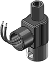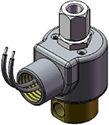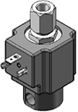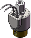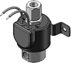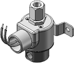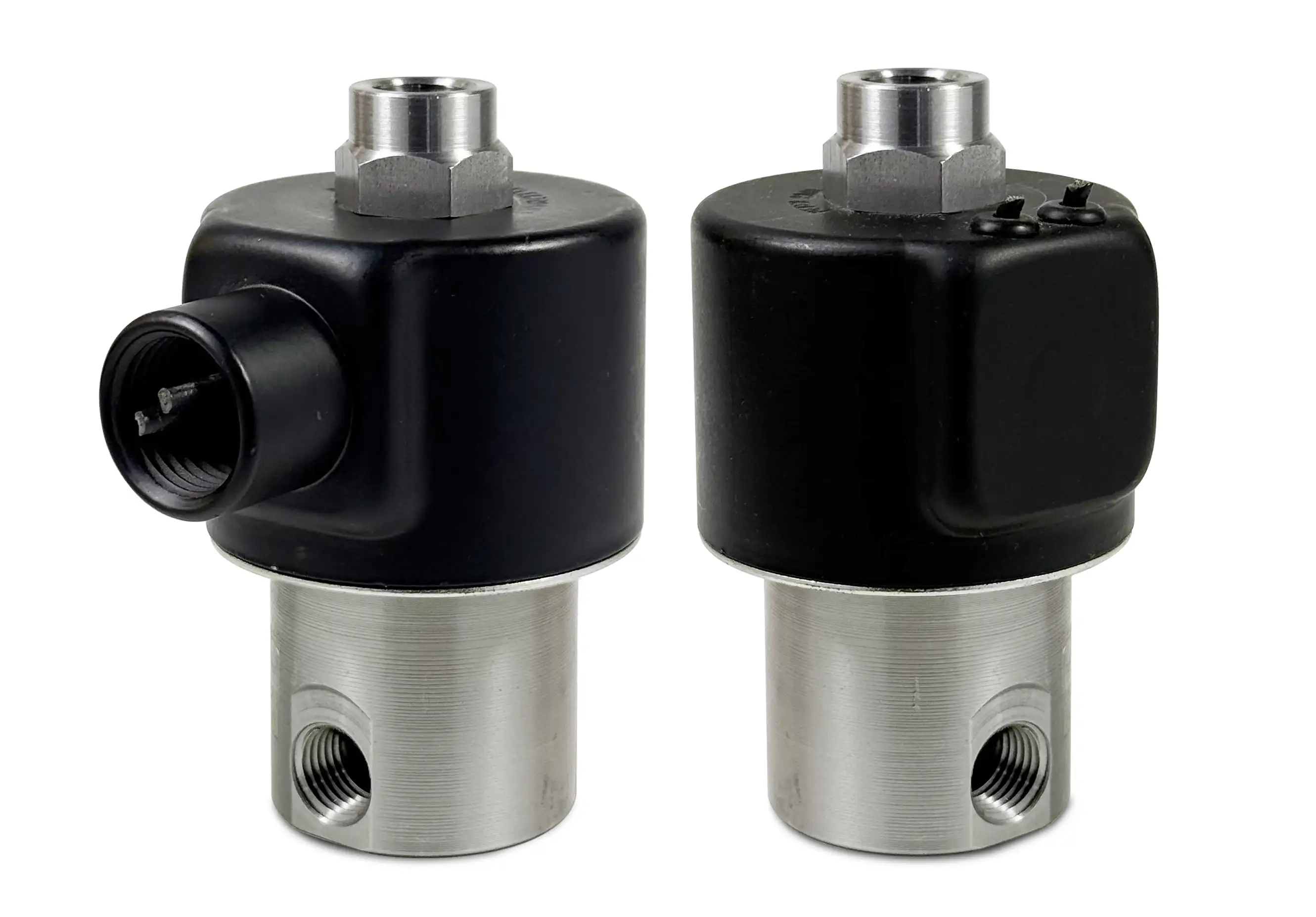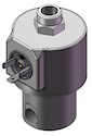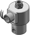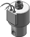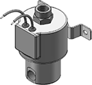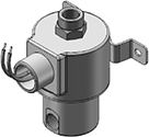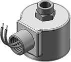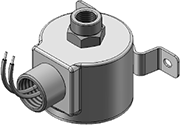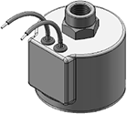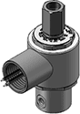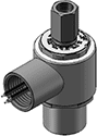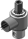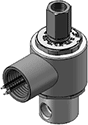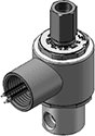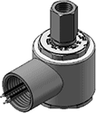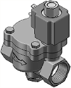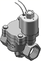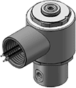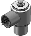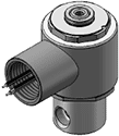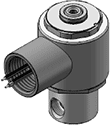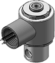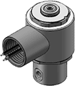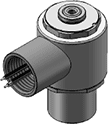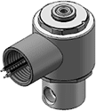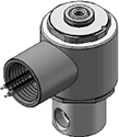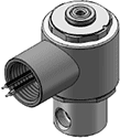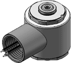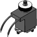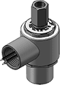
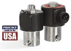
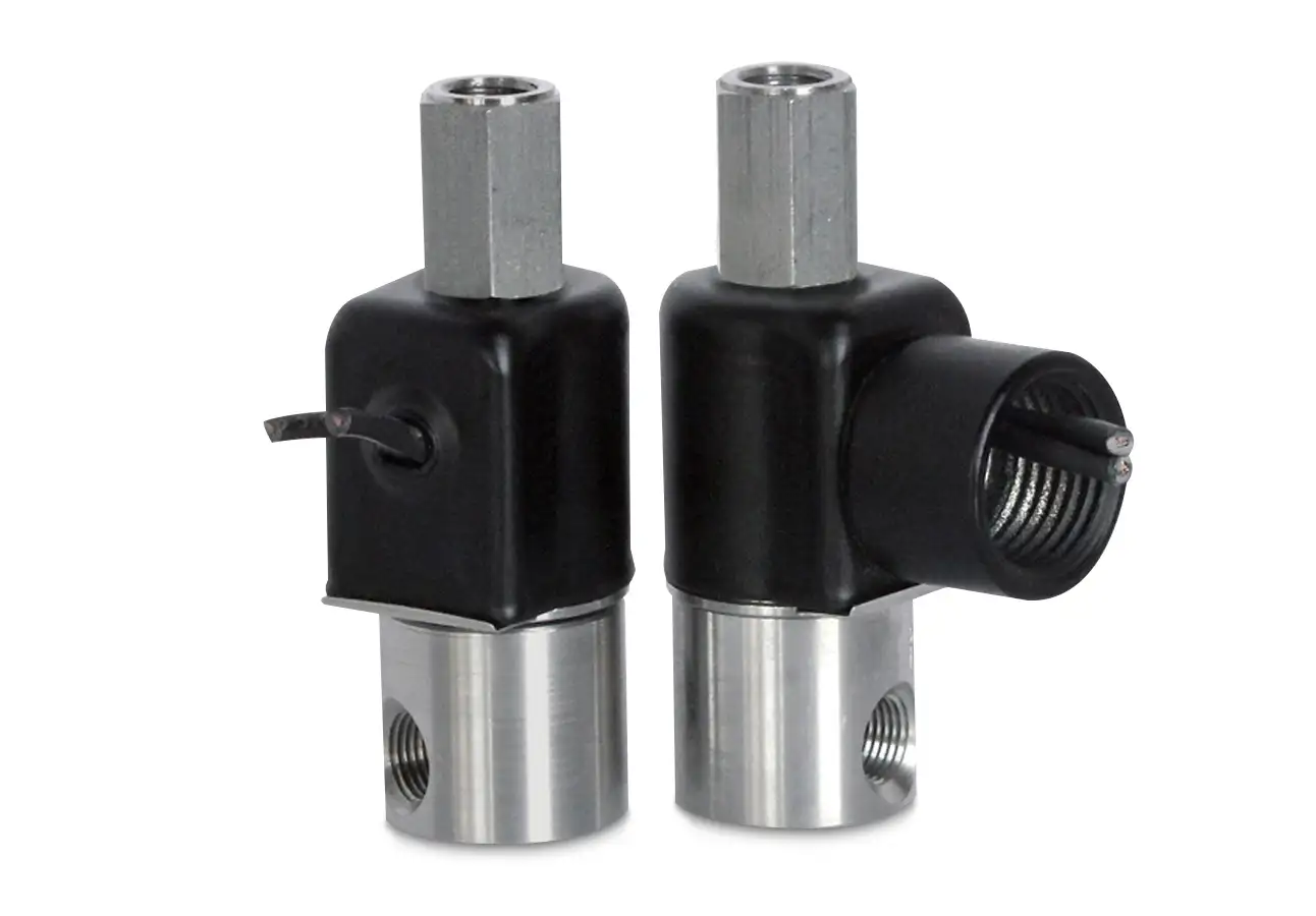
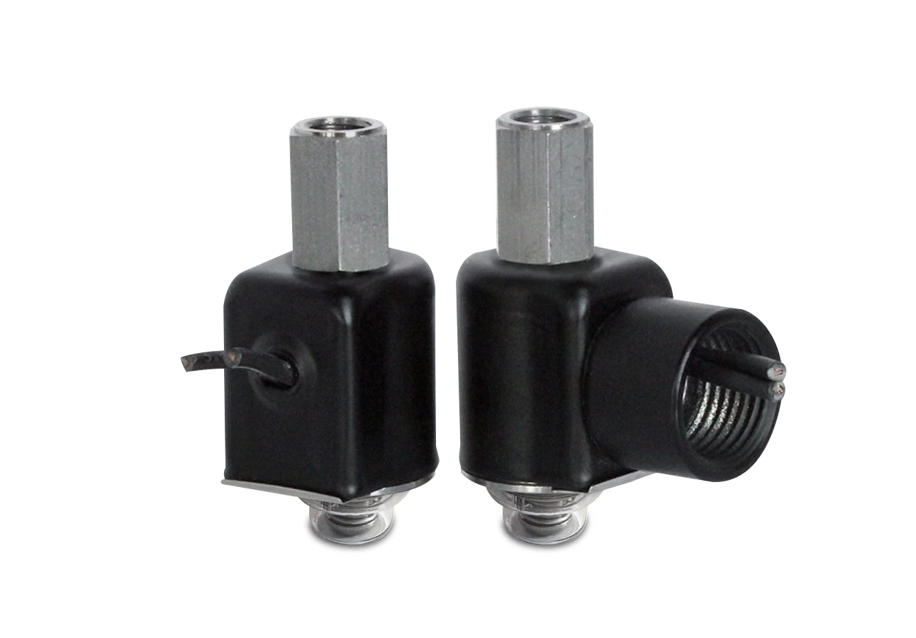
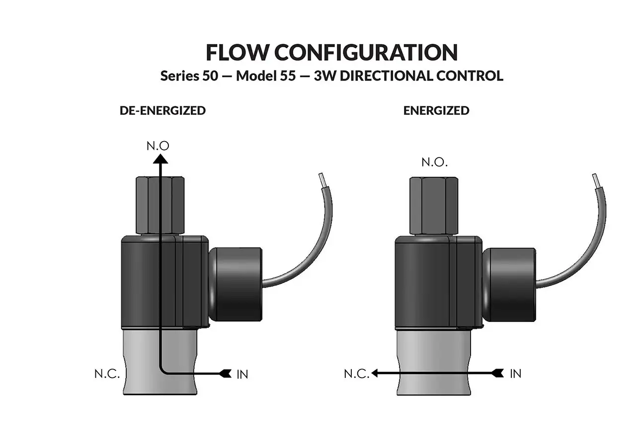
Series 50 Model 55

Series 50 Model 55
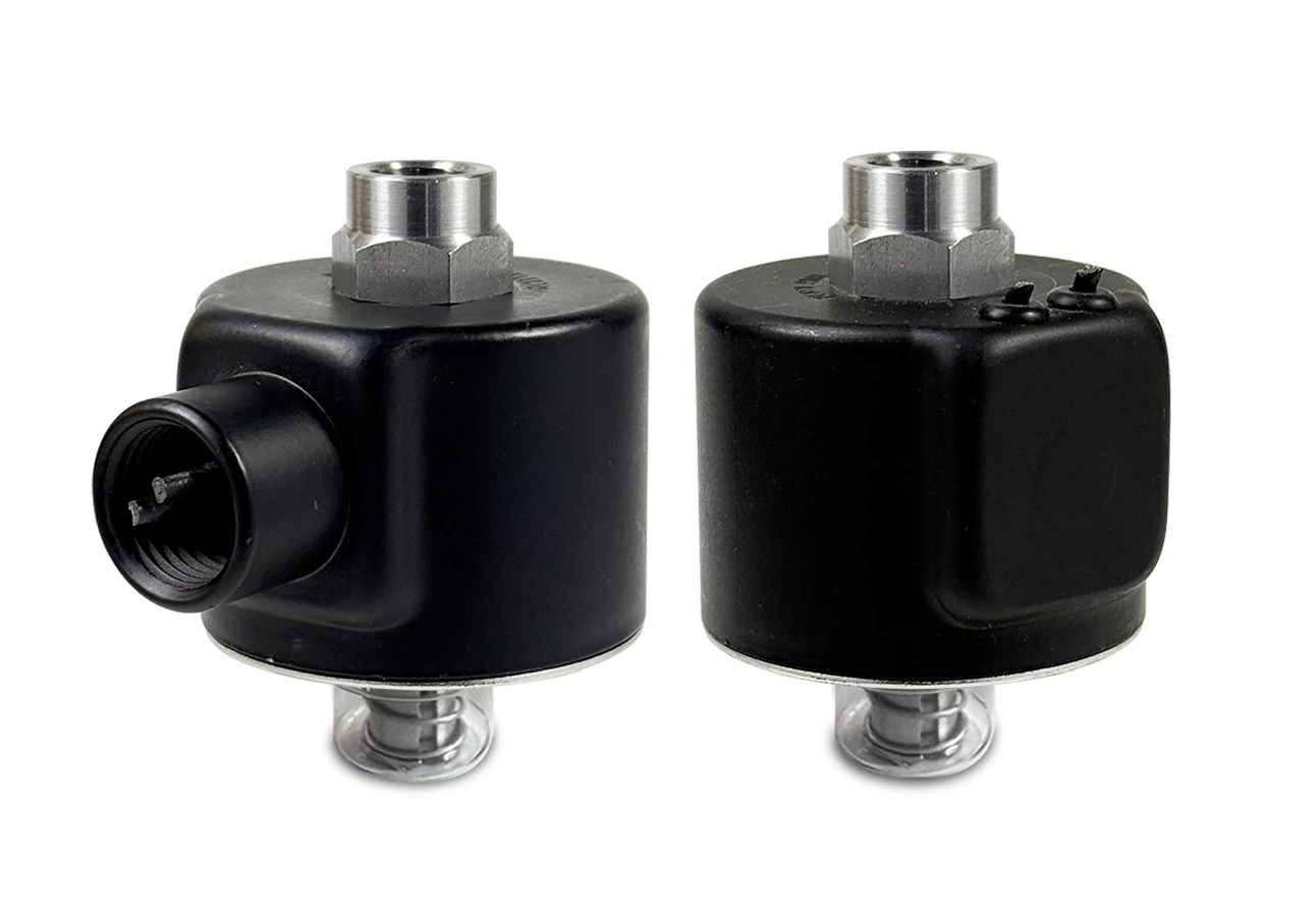
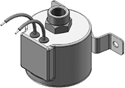
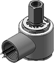
Series 50 Model 55 solenoid operator
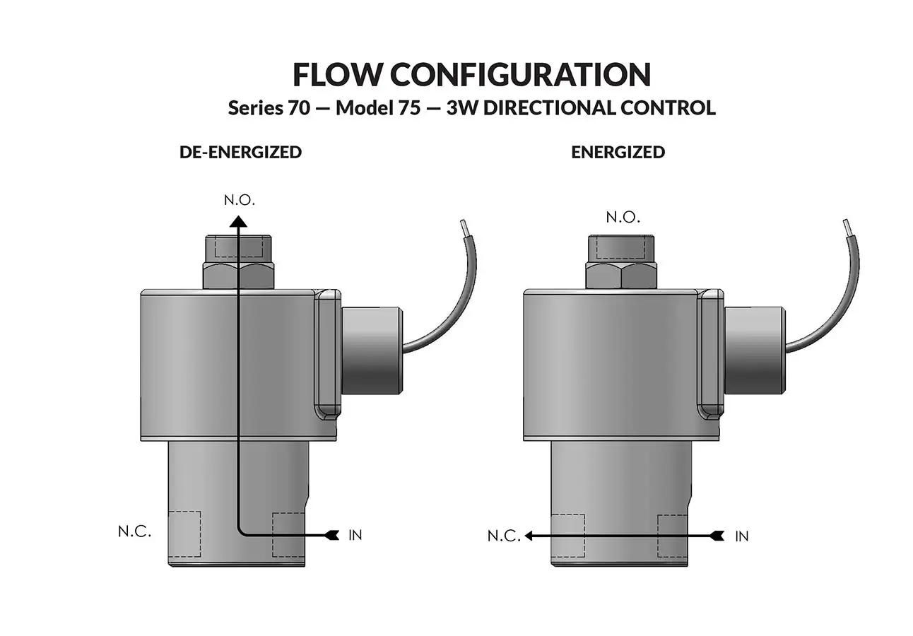
Series 50 Model 55 flow Diagram

Our original mini — engineered for space economy without sacrificing performance. Typical applications include medical, analytical instrumentation. Air, water, and other fluids compatible with standard Buna seals. Hot water, steam, gasoline, and many oils require special seal materials.

  • Tough with options to use in hazardous location environments or low watt applications.
  • High quality engineering.
Valve specifications — Series 50 Model 55
MAX. OPER.
PRESS. DIFF.
ORIFICE SIZECV FACTORVALVE NUMBER
GROMMET HOUSING
VALVE NUMBER
CONDUIT HOUSING
ACDCN.C.N.O.N.C.N.O.1/8 NPT PORTS1/8 NPT PORTS
3002001/321/32.022.02055GG8XGM55GG8XCM
2001003/643/64.055.04855HH8XGM55HH8XCM
100501/161/16.075.07555JJ8XGM55JJ8XCM
75253/321/16.156.07555KJ8XGM55KJ8XCM
75403/323/32.156.15055KK8XGM55KK8XCM
45251/83/32.230.15055NK8XGM55NK8XCM

Ordering Information:

When ordering valves or repair packs add voltage and frequency to complete valve number. For example: valve (55JJ8XGM 120/60) repair pack (K55JJX AC)

When ordering operators add the letter “O” to the front of the valve number, replace body port number with the letter “D”: example: operator (O55JJDXGM 120/60)


Coil Voltage
12/DC, 24/DC, 48/DC, 125/DC, 120/60-110/50, 240/60, and 24/60.
Nominal Power
AC — 6.0 Watts, DC — 7.0 Watts
Coil Construction
Molded and potted Class F. (Class H optional)
Typical Response Time on Air
4 - 16 Milliseconds
Operating Speed
Up to 600 CPM
Duty Cycle
Continuous
Internal Components
Stainless Steel. Copper – AC Only.
Elastomers
Nitrile (Buna) (Std.). Many other elastomers available.*
Orifice Diameter
See table above.
Porting
Standard 1/8" NPT (other ports available).*
Housing
Grommet and 1/2" NPT conduit - many options available.*
Listings
Most valves are UL and CSA listed.*
Life Expectancy
Millions of cycles, depending on application, lubrication, etc.
Valve Weight
Grommet Valve: 0.38 lb Conduit Valve: 0.44 lb
Repair Packs
See table above.
Options
Alternate Port Locations, Metering, Alternate Elastomers, Low Wattage, Spade Terminal Coil and Explosion Proof*
Media
Air, water, and other fluids compatible with standard Buna seals. Hot water, steam, gasoline, and many oils require special seal materials. (Series 50 pressure ratings may change due to the viscosity of the liquid.)*
Valve Temperature Range
Standard Valves – 0°F (-18°C) to 104°F (40°C) ambient; 0°F (-18°C) to 150°F (65°C) media. Optional Valves – can tolerate much higher or much lower ambient and media temperatures.*
Maximum Operating Pressure Differentials
See table above.
Burst Pressure
5000 PSI
Leakage
Bubble tight for standard valves.
Vacuum
To 5 Microns*

Series 50 General Purpose Valves Conduit

Technical drawing — MODEL 55 1/8-27 NPT 3-WAY DIRECTIONAL CONTROL CONDUIT CONNECTION
MODEL 55
1/8-27 NPT
3-WAY DIRECTIONAL CONTROL CONDUIT CONNECTION
Technical drawing — MODEL 55 STUD MOUNT BODY 3-WAY DIRECTIONAL CONTROL CONDUIT CONNECTION
MODEL 55
STUD MOUNT BODY
3-WAY DIRECTIONAL CONTROL CONDUIT CONNECTION
 

Series 50 General Purpose Valves Grommet

Technical drawing — MODEL 55 1/8-27 NPT 3-WAY DIRECTIONAL CONTROL GROMMET WITH LEADS
MODEL 55
1/8-27 NPT
3-WAY DIRECTIONAL CONTROL GROMMET WITH LEADS
Technical drawing — MODEL 55 STUD MOUNT BODY 3-WAY DIRECTIONAL CONTROL GROMMET WITH LEADS
MODEL 55
STUD MOUNT BODY
3-WAY DIRECTIONAL CONTROL GROMMET WITH LEADS
 

Series 50 General Purpose Valves Yoke Leads

Technical drawing — MODEL 55 1/8-27 NPT 3-WAY DIRECTIONAL CONTROL YOKE WITH LEADS
MODEL 55
1/8-27 NPT
3-WAY DIRECTIONAL CONTROL YOKE WITH LEADS
Technical drawing — MODEL 55 STUD MOUNT BODY 3-WAY DIRECTIONAL CONTROL YOKE WITH LEADS
MODEL 55
STUD MOUNT BODY
3-WAY DIRECTIONAL CONTROL YOKE WITH LEADS
 

Series 50 General Purpose Valves Yoke Spades

Technical drawing — MODEL 55 1/8-27 NPT 3-WAY DIRECTIONAL CONTROL YOKE WITH SPADE TERMINALS
MODEL 55
1/8-27 NPT
3-WAY DIRECTIONAL CONTROL YOKE WITH SPADE TERMINALS
Technical drawing — MODEL 55 STUD MOUNT BODY 3-WAY DIRECTIONAL CONTROL YOKE WITH SPADE TERMINALS
MODEL 55
STUD MOUNT BODY
3-WAY DIRECTIONAL CONTROL YOKE WITH SPADE TERMINALS
 
Stainless Steel (Std.), Brass (Opt.) or Aluminum (Opt.)

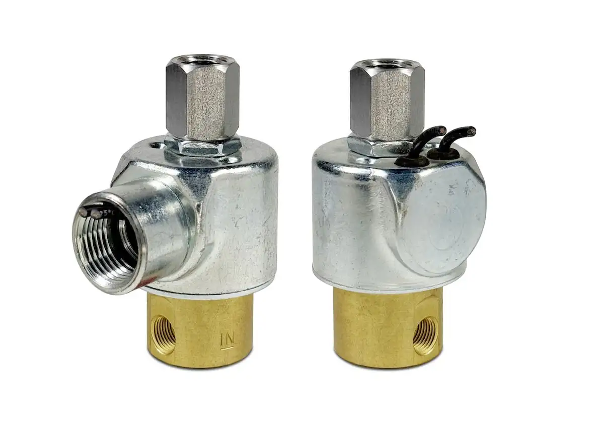
Series 30 Model 35

Series 30 Model 35
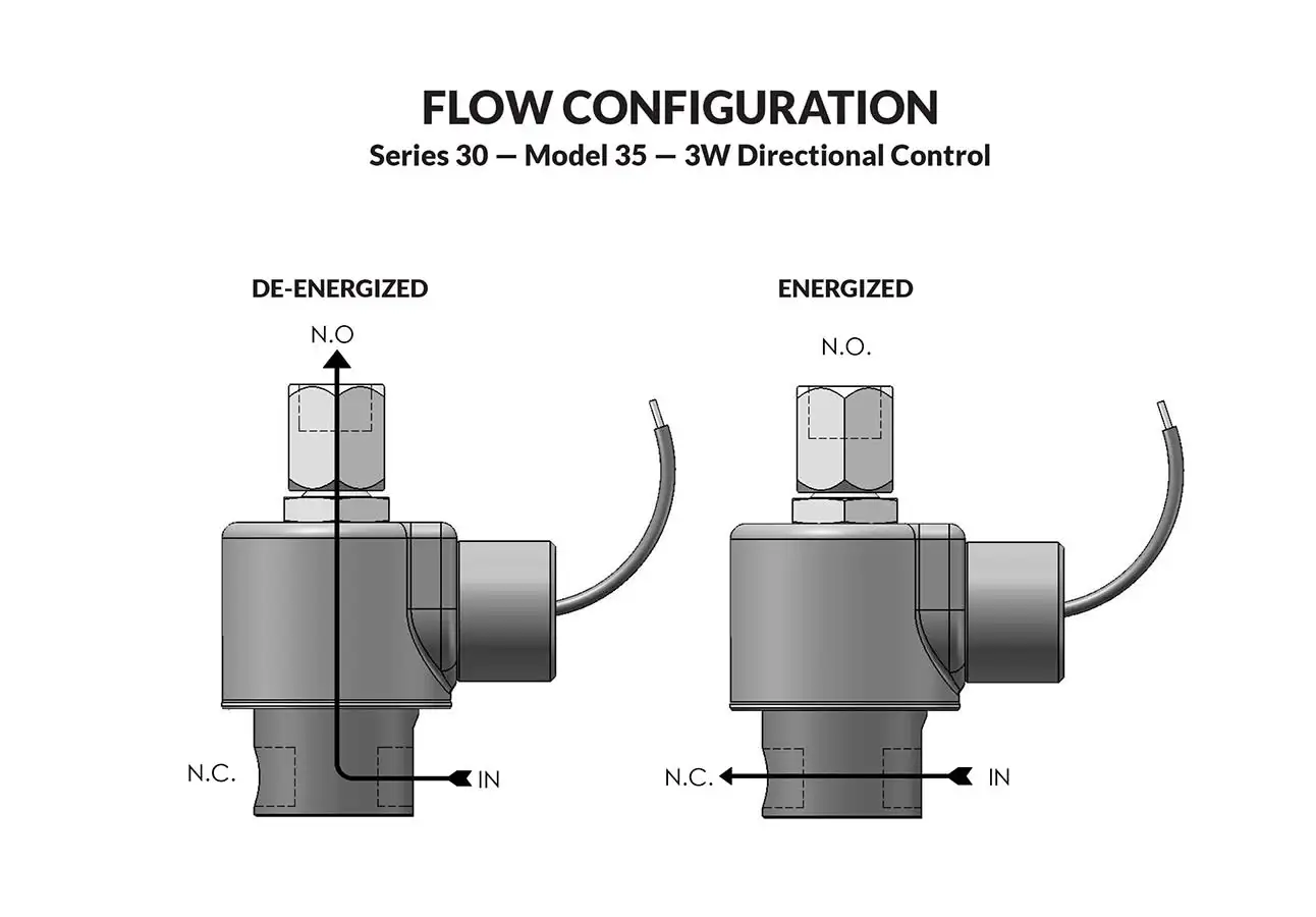
Series 30 Model 35 flow diagram

Complete range of valves particularly suitable when cost and size are major factors. The bodies are constructed of brass (stainless steel is optional). Air, water, and other fluids compatible with standard Buna seals. Hot water, steam, gasoline, and many oils require special seal materials.

  • Brass body with stainless steel internal construction.
  • A smaller, cost effective alternative to any industry standard.
Valve specifications — Series 30 Model 35
MAX. OPER.
PRESS. DIFF.
ORIFICE SIZECV FACTORVALVE NUMBER
GROMMET HOUSING
VALVE NUMBER
CONDUIT HOUSING
ACDCN.C.N.O.N.C.N.O.1/8 NPT PORTS1/8 NPT PORTS
3003001/321/32.024.02435GG5XGM35GG5XCM
1751753/641/16.052.09535HJ5XGM35HJ5XCM
1251251/161/16.095.09535JJ5XGM35JJ5XCM
75753/323/32.160.16035KK5XGM35KK5XCM
50501/83/32.275.16035NK5XGM35NK5XCM

Ordering Information:

When ordering valves or repair packs add voltage and frequency to complete valve number. For example: valve (35HJ5XGM 120/60) repair pack (K35HJX AC)

When ordering operators add the letter “O” to the front of the valve number, replace body port number with the letter “D”: example: operator (O35HJDXGM 120/60)


Coil Voltage
12/DC, 24/DC, 48/DC, 125/DC, 120/60-110/50, 240/60, and 24/60.
Nominal Power
AC — 8.0 Watts DC — 8.0 Watts
Coil Construction
Molded (Std.), Non-molded Class A and Potted Class F or Class H (Opt.)
Typical Response Time on Air
4 - 16 Milliseconds
Operating Speed
Up to 600 CPM
Duty Cycle
Continuous
Internal Components
Stainless Steel. Copper – AC Only.
Elastomers
Nitrile (Buna) (Std.). Many other elastomers available.*
Orifice Diameter
See table above.
Porting
Standard 1/8" NPT (other ports available).*
Housing
Grommet and 1/2″ NPT conduit – many options available.*
Listings
Most valves are UL and CSA listed.*
Life Expectancy
Millions of cycles, depending on application, lubrication, etc.
Valve Weight
Grommet Valve: 0.75 lb Conduit Valve: 0.81 lb
Repair Packs
See table above.
Options
Alternate Port Locations, Metering, Manual Override, Alternate Elastomers, Spade Terminal Coil*
Media
Air, water, and other fluids compatible with standard Buna seals. Hot water, steam, gasoline, and many oils require special seal materials. (Series 30 pressure ratings may change due to the viscosity of the liquid.)*
Valve Temperature Range
Standard Valves – 0°F (-18°C) to 104°F (40°C) ambient; 0°F (-18°C) to 150°F (65°C) media. Optional Valves – can tolerate much higher or much lower ambient and media temperatures.*
Maximum Operating Pressure Differentials
See table above.
Burst Pressure
5000 PSI
Leakage
Bubble tight for standard valves.
Vacuum
To 5 Microns*

Series 30 General Purpose Valves Conduit

Technical drawing — MODEL 35 1/8-27 NPT 3-WAY DIRECTIONAL CONTROL CONDUIT CONNECTION
MODEL 35
1/8-27 NPT
3-WAY DIRECTIONAL CONTROL CONDUIT CONNECTION


Series 30 General Purpose Valves DIN

Technical drawing — MODEL 35 1/8-27 NPT 3-WAY DIRECTIONAL CONTROL DIN STYLE COIL
MODEL 35
1/8-27 NPT
3-WAY DIRECTIONAL CONTROL DIN STYLE COIL


Series 30 General Purpose Valves Grommet

Technical drawing — MODEL 35 1/8-27 NPT 3-WAY DIRECTIONAL CONTROL GROMMET WITH LEADS
MODEL 35
1/8-27 NPT
3-WAY DIRECTIONAL CONTROL GROMMET WITH LEADS


Series 30 General Purpose Valves Grommet/Bracket Connection

Technical drawing — MODEL 35 1/8-27 NPT 3-WAY DIRECTIONAL CONTROL GROMMET/BRACKET WITH LEADS
MODEL 35
1/8-27 NPT
3-WAY DIRECTIONAL CONTROL GROMMET/BRACKET WITH LEADS

Minimum quantity required. Please contact sales for additional assistance.
sales@peterpaul.com
 

Series 30 General Purpose Valves Conduit/Bracket Connection

Technical drawing — MODEL 35 1/8-27 NPT 3-WAY DIRECTIONAL CONTROL CONDUIT/BRACKET CONNECTION
MODEL 35
1/8-27 NPT
3-WAY DIRECTIONAL CONTROL CONDUIT/BRACKET CONNECTION

Minimum quantity required. Please contact sales for additional assistance.
sales@peterpaul.com
 
Brass (Std.) or Stainless Steel (Opt.)
Series 70 Model 75

Series 70 Model 75
Series 70 Model 75 solenoid operator
Series 70 Model 75 flow diagram

Super valves that have ratings that formerly required valves of much greater size. Air, water, and other fluids compatible with standard Buna seals. Hot water, steam, gasoline, and many oils require special seal materials.

  • Largest direct acting (non-piloted) valve we manufacture.
  • Large orifice.
  • High flow.
  • Will operate effectively at very low pressures or vacuum.
Valve specifications — Series 70 Model 75
MAX. OPER.
PRESS. DIFF.
ORIFICE SIZECV FACTORVALVE NUMBER
GROMMET HOUSING
VALVE NUMBER
CONDUIT HOUSING
ACDCN.C.N.O.N.C.NO1/4 NPT PORTS1/4 NPT PORTS
3503501/161/16.09.0975JJ9ZGM75JJ9ZCM
2502503/323/32.22.2275KK9ZGM75KK9ZCM
1751751/81/8.35.3575NN9ZGM75NN9ZCM
1251255/325/32.45.4575OO9ZGM75OO9ZCM
1001003/163/16.50.5075PP9ZGM75PP9ZCM

Ordering Information:

When ordering valves or repair packs add voltage and frequency to complete valve number. For example: valve (75OO9ZGM 120/60) repair pack (K75OOX AC)

When ordering operators add the letter “O” to the front of the valve number, replace body port number with the letter “D”: example: operator (O75OODZGM 120/60)


Coil Voltage
12/DC, 24/DC, 48/DC, 125/DC, 120/60-110/50, 240/60, and 24/60.
Nominal Power
AC — 18.0 Watts DC — 16.0 Watts
Coil Construction
Molded Class F (Std.), Potted and Class H Option
Typical Response Time on Air
4 – 16 Milliseconds
Operating Speed
Up to 600 CPM
Duty Cycle
Continuous
Internal Components
Stainless Steel. Copper – AC Only.
Elastomers
Nitrile (Buna) (Std.). Many other elastomers available.*
Orifice Diameter
See table above.
Porting
Standard 1/4" NPT (other ports available).*
Housing
Grommet and 1/2" NPT conduit - many options available.*
Listings
Most valves are UL and CSA listed.*
Life Expectancy
Millions of cycles, depending on application, lubrication, etc.
Valve Weight
Grommet Valve: 2.00 lb Conduit Valve: 2.06 lb
Repair Packs
See table above.
Options
Alternate Port Locations, Metering and Alternate Elastomers
Media
Air, water, and other fluids compatible with standard Buna seals. Hot water, steam, gasoline, and many oils require special seal materials. (Series 70 pressure ratings may change due to the viscosity of the liquid.)*
Valve Temperature Range
Standard Valves – 0°F (-18°C) to 104°F (40°C) ambient; 0°F (-18°C) to 150°F (65°C) media. Optional Valves – can tolerate much higher or much lower ambient and media temperatures.*
Maximum Operating Pressure Differentials
See table above.
Burst Pressure
4000 PSI
Leakage
Bubble tight for standard valves.
Vacuum
To 5 Microns*

Series 70 3-WAY DIRECTION CONTROL DIN STYLE COIL

Technical drawing — MODEL 75 1/4-18 NPT 3-WAY DIRECTIONAL CONTROL DIN STYLE COIL
MODEL 75
1/4-18 NPT
3-WAY DIRECTIONAL CONTROL DIN STYLE COIL


Series 70 General Purpose Valves Conduit

Technical drawing — MODEL 75 1/4-18 NPT 3-WAY DIRECTIONAL CONTROL CONDUIT CONNECTION
MODEL 75
1/4-18 NPT
3-WAY DIRECTIONAL CONTROL CONDUIT CONNECTION


Series 70 General Purpose Valves Grommet

Technical drawing — MODEL 75 1/4-18 NPT 3-WAY DIRECTIONAL CONTROL GROMMET WITH LEADS
MODEL 75
1/4-18 NPT
3-WAY DIRECTIONAL CONTROL GROMMET WITH LEADS


Series 70 General Purpose Valves Grommet/Bracket Connection

Technical drawing — MODEL 75 1/4-18 NPT 3-WAY DIRECTIONAL CONTROL GROMMET/BRACKET CONNECTION
MODEL 75
1/4-18 NPT
3-WAY DIRECTIONAL CONTROL GROMMET/BRACKET CONNECTION

Minimum quantity required. Please contact sales for additional assistance.
sales@peterpaul.com
 

Series 70 General Purpose Valves Conduit/Bracket Connection

Technical drawing — MODEL 75 1/4-18 NPT 3-WAY DIRECTIONAL CONTROL CONDUIT/BRACKET CONNECTION
MODEL 75
1/4-18 NPT
3-WAY DIRECTIONAL CONTROL CONDUIT/BRACKET CONNECTION

Minimum quantity required. Please contact sales for additional assistance.
sales@peterpaul.com
 
Stainless Steel (Std.) or Brass (Opt.)
Series 70 Operators Conduit

Technical drawing — MODEL O75 3-WAY DIRECTIONAL CONTROL CONDUIT CONNECTION
MODEL O75 3-WAY DIRECTIONAL CONTROL CONDUIT CONNECTION

Series 70 Operators Conduit/Bracket Connection

Technical drawing — MODEL O75 3-WAY DIRECTIONAL CONTROL CONDUIT/BRACKET CONNECTION
MODEL O75 3-WAY DIRECTIONAL CONTROL CONDUIT/BRACKET CONNECTION

Series 70 Operators Grommet

Technical drawing — MODEL O75 3-WAY DIRECTIONAL CONTROL GROMMET HOUSING WITH LEADS
MODEL O75 3-WAY DIRECTIONAL CONTROL GROMMET HOUSING WITH LEADS

Series 70 Operators Grommet/Bracket Connection

Technical drawing — MODEL O75 3-WAY DIRECTIONAL CONTROL GROMMET/BRACKET HOUSING WITH LEADS
MODEL O75 3-WAY DIRECTIONAL CONTROL GROMMET/BRACKET HOUSING WITH LEADS

Series E50 Model E55

Series E50 Model E55
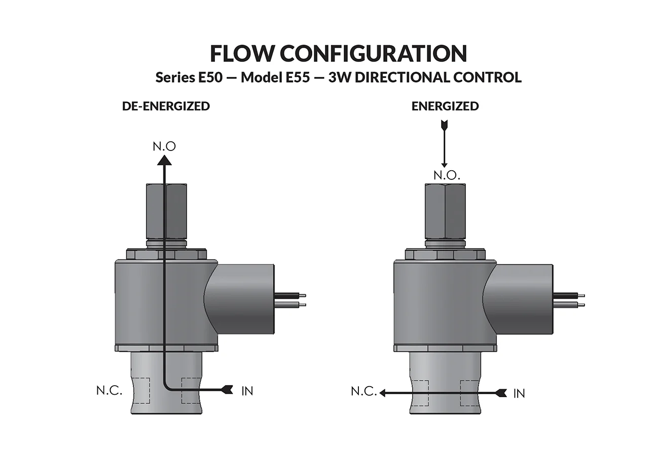
Series E50 Model E55 flow diagram

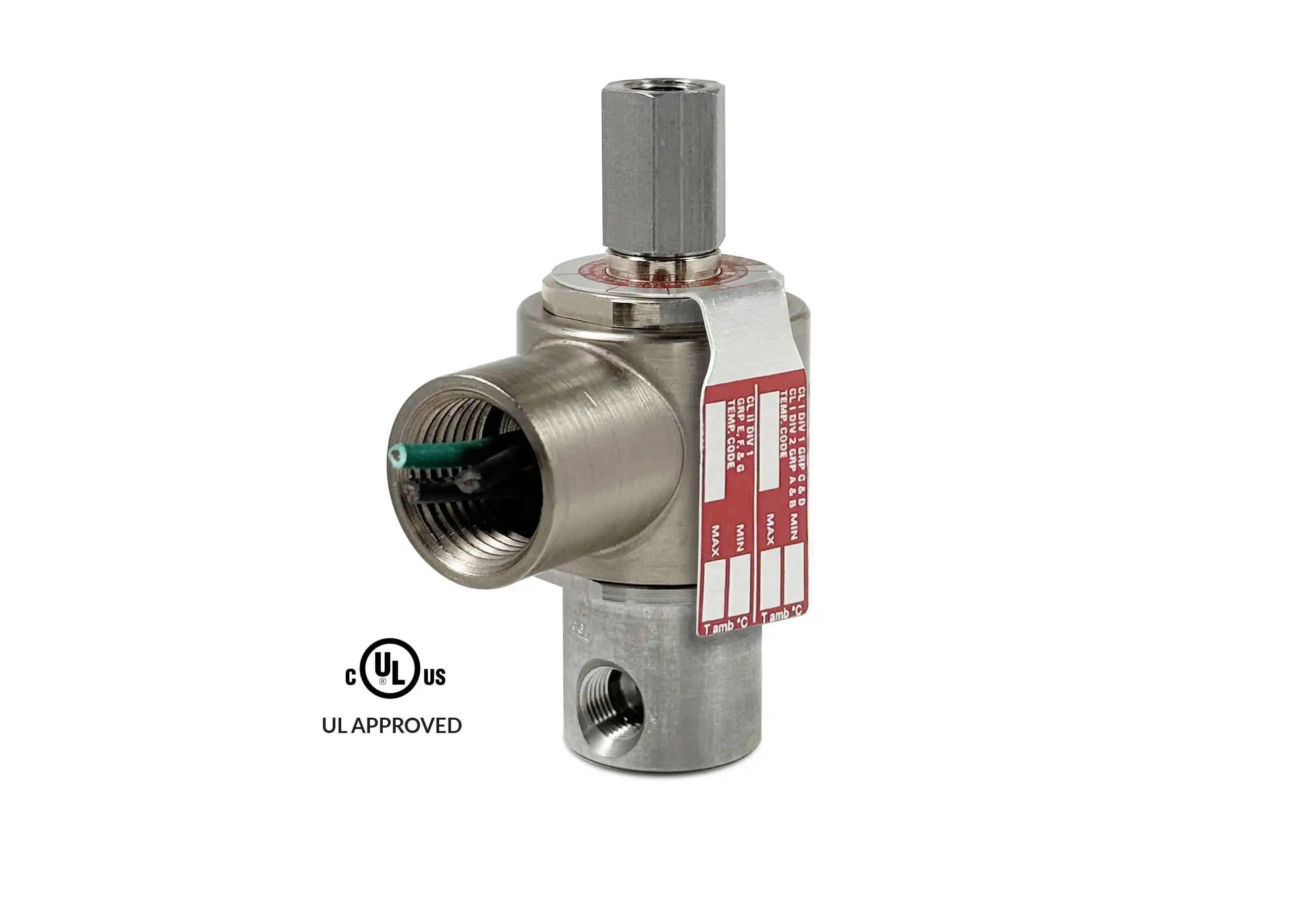
PeterPaul explosion proof valves are used where fire or explosion hazards exist due to the presence of flammable gases or vapors, flammable liquids, combustible dust, or easily ignitable fibers. Hazardous Location valves are recommended, or in some cases compulsory, where a high level of protection from explosion is required.

  • Miniature Hazardous Location valve.
  • Flame-Proof construction.
  • High quality engineering.
Valve specifications — Series E50 Model E55
MAX. OPER.
PRESS. DIFF.
ORIFICE SIZECV FACTORNORTH AMERICAN
VALVE NUMBER
IECEx/ATEX
VALVE NUMBER
ACDCN.C.N.O.N.C.N.O.
3002001/321/32.022.020E55GG8XCCM-∆EA55GG8XCCM-∆
2001003/643/64.055.048E55HH8XCCM-∆EA55HH8XCCM-∆
100501/161/16.075.075E55JJ8XCCM-∆EA55JJ8XCCM-∆
75253/321/16.156.075E55KJ8XCCM-∆EA55KJ8XCCM-∆
75403/323/32.156.156E55KK8XCCM-∆EA55KK8XCCM-∆
65201/81/16.230.075E55NJ8XCCM-∆EA55NJ8XCCM-∆
45201/83/32.230.156E55NK8XCCM-∆EA55NK8XCCM-∆

Ordering Information:

Seal Material: Replace ∆ with desired code - Blank = Nitrile (Buna) S = Low Temp Buna. N = FKM* E = Neoprene A = EPDM

When ordering valves or repair packs add voltage and frequency to complete valve number. For example: valve (E55KJ8XCCM 120/60) repair pack (5KE55KJ AC)

When ordering operators add the letter “O” to the front of the valve number, replace body port number with the letter “D”: example: operator (OE55KJDXCCM 120/60)


Coil Voltage
12/DC, 24/DC, 48/DC, 125/DC, 120/60-110/50, 240/60, and 24/60.
Nominal Power
AC — 5.6 Watts DC — 7.2 Watts
Coil Construction
Molded Class F with third wire ground (Std.), Class H or Potted (Opt.)
Typical Response Time on Air
4 - 16 Milliseconds
Operating Speed
Up to 600 CPM
Duty Cycle
Continuous
Internal Components
Stainless Steel. Copper – AC Only.
Elastomers
Nitrile (Buna) (Std.). Many other elastomers available.*
Orifice Diameter
See table above.
Porting
1/8" NPT (Std.)
Housing
Flame-Proof construction with 1/2" NPT conduit
Listings
Valves are UL listed and CSA certified for Hazardous Locations — Class I, Div 1, Group C and D - Class II, Div 1, Groups E, F, and G; Div 2, Groups A, B, C, D, E, F, and G
Life Expectancy
Millions of cycles, depending on application, lubrication, etc.
Valve Weight
0.65 lbs
Repair Packs
See table above.
Options
Alternate Port Locations, Metering, Alternate Elastomers, All Stainless Steel Construction*
Media
Air, and other fluids compatible with standard Buna seals. Hot water, steam, gasoline, oils, some hydraulic fluids, and many media require special seal materials. (Series 50 pressure ratings may change due to the viscosity of the liquid.)*
Valve Temperature Range
Standard Valves – 0°F (-18°C) to 104°F (40°C) ambient; 0°F (-18°C) to 150°F (65°C) media. Optional Valves – can tolerate much higher or much lower ambient and media temperatures.*
Maximum Operating Pressure Differentials
See table above.
Burst Pressure
5000 PSI
Leakage
Bubble tight for standard valves.
Vacuum
To 5 Microns*

Series E50 Hazardous Location Valves

Technical drawing — MODEL E55 1/8-27 NPT 3-WAY DIRECTIONAL CONTROL EXPLOSION PROOF
MODEL E55
1/8-27 NPT
3-WAY DIRECTIONAL CONTROL EXPLOSION PROOF

Technical drawing — MODEL E55 10-32 PORTS 3-WAY DIRECTIONAL CONTROL EXPLOSION PROOF
MODEL E55
10-32 PORTS
3-WAY DIRECTIONAL CONTROL EXPLOSION PROOF

Technical drawing — MODEL E55 BODY OPTION "E" 3-WAY DIRECTIONAL CONTROL EXPLOSION PROOF
MODEL E55
BODY OPTION "E"
3-WAY DIRECTIONAL CONTROL EXPLOSION PROOF

Technical drawing — MODEL E55 BODY OPTION "O" 3-WAY DIRECTIONAL CONTROL EXPLOSION PROOF
MODEL E55
BODY OPTION "O"
3-WAY DIRECTIONAL CONTROL EXPLOSION PROOF

Technical drawing — MODEL E55 BODY OPTION "R" 3-WAY DIRECTIONAL CONTROL EXPLOSION PROOF
MODEL E55
BODY OPTION "R"
3-WAY DIRECTIONAL CONTROL EXPLOSION PROOF

Technical drawing — MODEL E55 METERED BODY 3-WAY DIRECTIONAL CONTROL EXPLOSION PROOF
MODEL E55
METERED BODY
3-WAY DIRECTIONAL CONTROL EXPLOSION PROOF

Minimum quantity required. Please contact sales for additional assistance.
sales@peterpaul.com
 
Stainless Steel (Std.)

Series 50 Operators Explosion Proof

Technical drawing — MODEL OE55 3-WAY DIRECTIONAL CONTROL EXPLOSION PROOF
MODEL OE55 3-WAY DIRECTIONAL CONTROL EXPLOSION PROOF
Certification
North American
IECEx/ATEX
IECEx/ATEX Nomenclature

Coming soon.

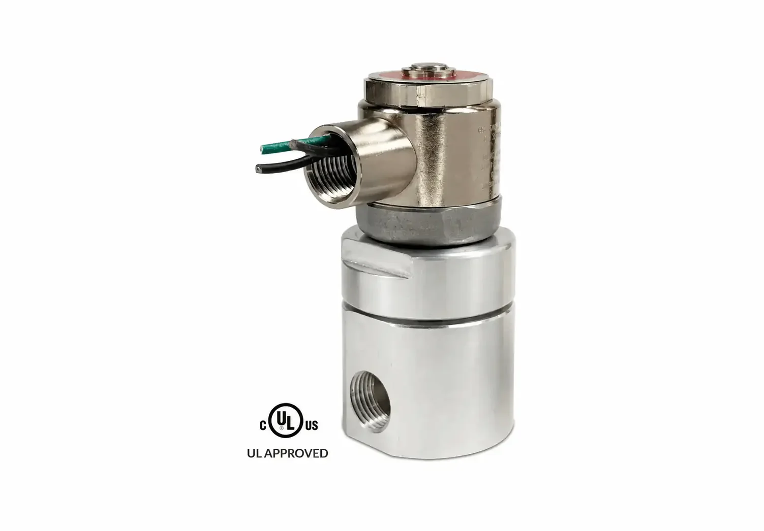
Series 80 Model E829 C/I Rated

Series 80 Model E829 C/I Rated
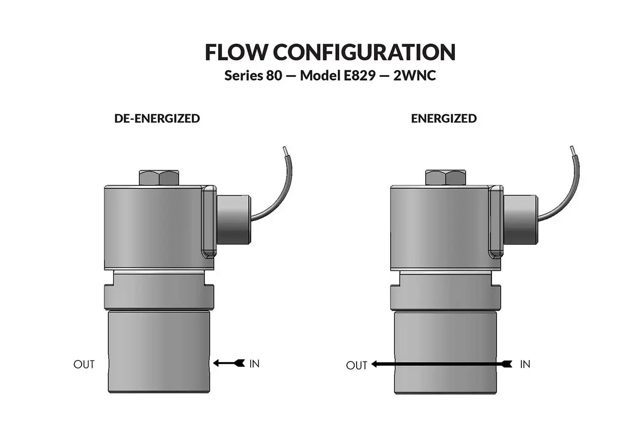
Series 80 Model E829 C/I Rated flow diagram

PeterPaul offers a line of Hazardous Location rated, large orifice Automatic Safety Shut Off Valves designed specifically for gas appliances. These valves meet the standards for Commercial/Industrial Safety Shut Off Valves per ANSI Z21.21 / CSA 6.5. They are well suited for use in heating equipment, furnaces, ovens, kilns, boilers, and gas generators.

Valve specifications — Series 80 Model E829 C/I Rated
MAX. OPER.
PRESS. DIFF.
MIN. OPER.
PRESS. DIFF.
GAS CAPACITY
BTU/Hr
CV FACTORPIPE SIZENORTH AMERICAN
VALVE NUMBER
ACDC
606002,751,0003.01/2 NPTE829B11DCCP-SC

Ordering Information:

When ordering valves or repair packs add voltage and frequency to complete valve number. For example: valve (829B11DGM 120/60) repair pack (K829BD AC)

No operator available


Coil Voltage
120/60 and 12, 24/DC
Nominal Power
9.5 watts DC, 7.3 watts AC
Coil Construction
Potted Class F
Operating Speed
Up to 100 CPM
Duty Cycle
Continuous
Internal Components
Stainless Steel. Copper – AC Only.
Elastomers
Nitrile (Buna) (Std.).
Housing
1/2" NPT conduit
Listings
Valves are UL listed and CSA certified for Hazardous Locations — Class I, Div 1, Group C and D – Class II, Div 1, Group E, F, and G
Life Expectancy
Millions of cycles, depending on application, lubrication, etc.
Repair Packs
See table above.
Media
Fuel gas.
Valve Temperature Range
– 40°F (-40°C) to 150°F (65°C) ambient and media.
Maximum Operating Pressure Differentials
See table above.
Burst Pressure
1000 PSI
Leakage
Bubble tight.

Series 80 Internal Pilot Valve - Explosion Proof Housing

Technical drawing — MODEL E829 1/2" NPT PORTS 2WNC EXPLOSION PROOF
MODEL E829 
1/2" NPT PORTS 2WNC EXPLOSION PROOF

 
Aluminum
Certification
North American

Series 80 Model 818

Series 80 Model 818
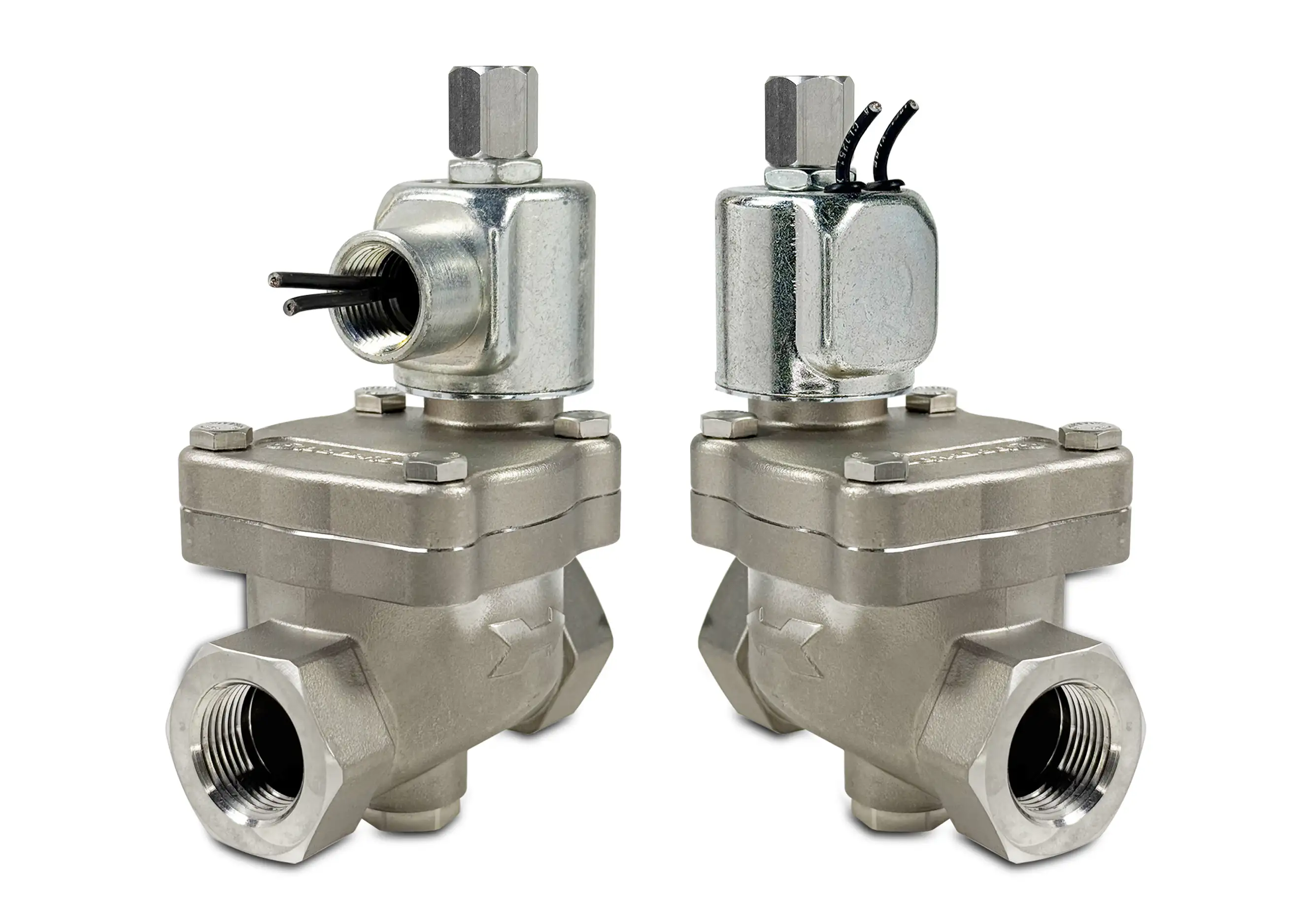
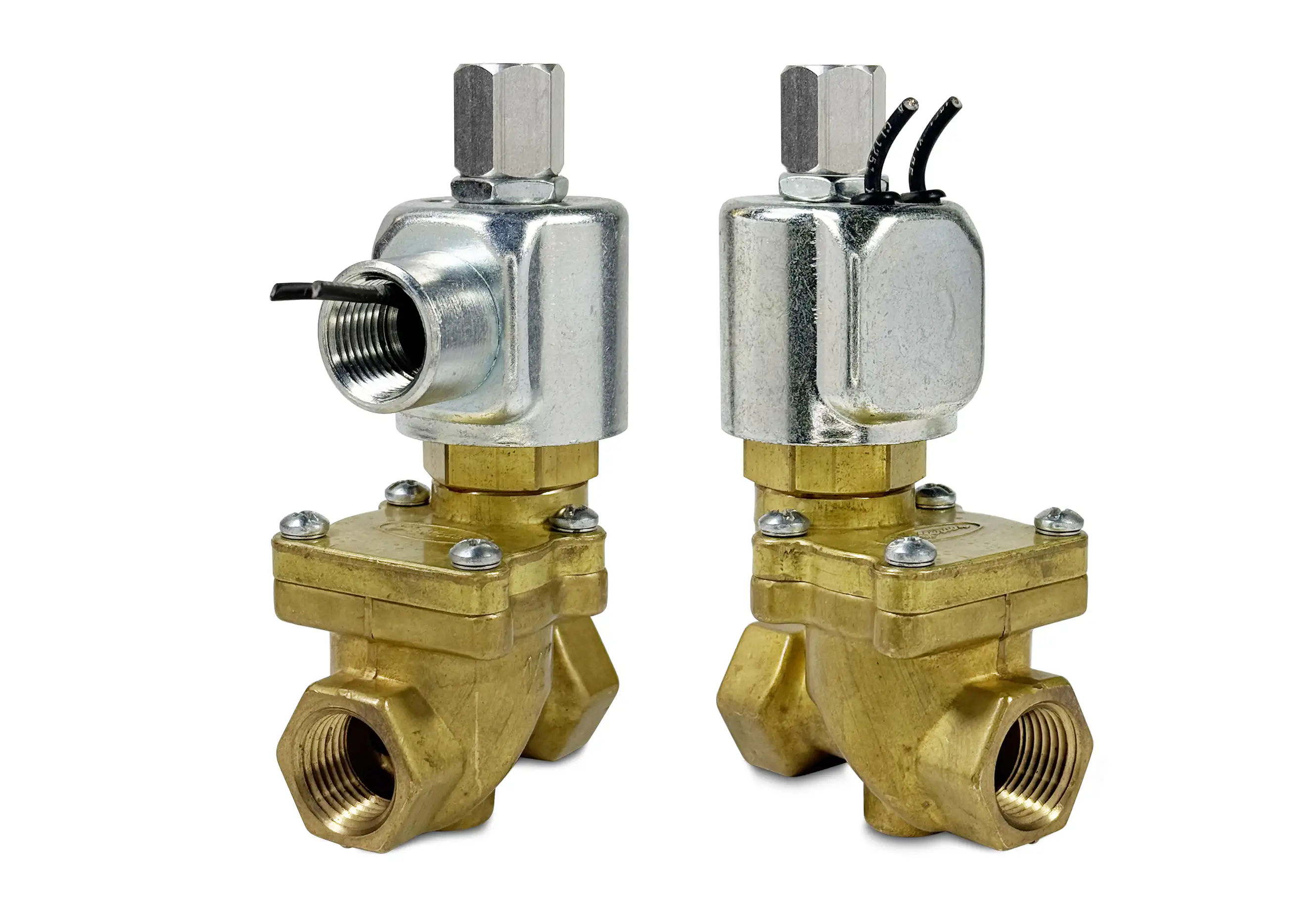
Series 80 Model 818 - Brass
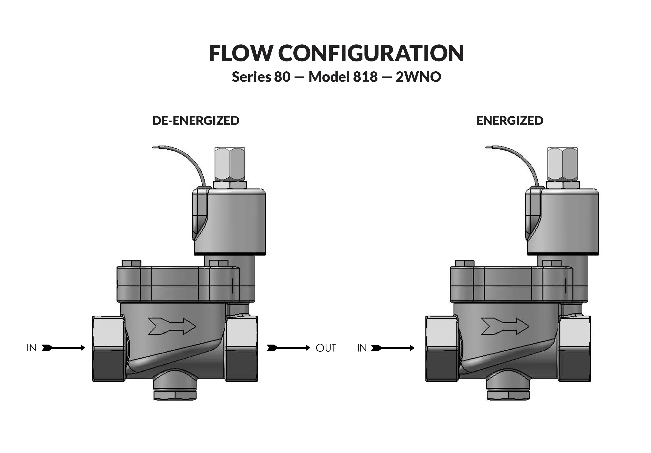
Series 80 Model 818 flow diagram

PeterPaul offers a line of large orifice solenoid valves to address process industry requirements for high flow rate or quick dump and fill capacity. These AC or DC powered valves are also suited for low pressure gas and liquid applications. Port sizes for the two way normally open version range are 1/2” NPT or 1” NPT with pressure ratings from 3 to 100 PSI.

  • Large orifice sizes for high flow applications.
  • Body is made of brass and stainless steel.
  • Operate on differential pressure — Internal Pilot.
  • NPT threaded connections.
  • Same coils and housings as our popular 20 Series.
Valve specifications — Series 80 Model 818
MAX. OPER. PRESS. DIFF.MIN. OPER. PRESS. DIFF.ORIFICE SIZECV FACTORVALVE NUMBER
GROMMET HOUSING
VALVE NUMBER
CONDUIT HOUSING
ACDCN.O.
10010031/24.0818B12DGM818B12DCM
1001003113.0818D23DGM818D23DCM

Ordering Information:

When ordering valves or repair packs add voltage and frequency to complete valve number. For example: valve (818B12DCM 120/60) repair pack (K818BDD AC)

No operator available


Coil Voltage
12/DC, 24/DC, 48/DC, 125/DC, 120/60-110/50, 240/60, and 24/60.
Nominal Power
AC — 7.7 Watts, DC — 9.5 Watts
Coil Construction
Molded (Std.), Non-molded Class A and Potted Class F or Class H (Opt.)
Operating Speed
Up to 100 CPM
Duty Cycle
Continuous
Internal Components
Stainless Steel. Copper – AC Only.
Elastomers
Nitrile (Buna) (Std.).
Orifice Diameter
See table above.
Housing
Grommet and 1/2″ NPT conduit
Life Expectancy
Millions of cycles, depending on application, lubrication, etc.
Repair Packs
See table above.
Options
Spade Terminal Coil and DIN
Media
Air, water, and oil. (Series 80 pressure ratings may change due to the viscosity of the liquid.)*
Valve Temperature Range
Standard Valves – 0°F (-18°C) to 104°F (40°C) ambient; 0°F (-18°C) to 150°F (65°C) media. Optional Valves – can tolerate much higher or much lower ambient and media temperatures.*
Maximum Operating Pressure Differentials
100 PSI
Leakage
Bubble tight

Series 80 Internal Pilot Valves Conduit

Technical drawing — MODEL 818 1/2" NPT PORTS 2WNO CONDUIT
MODEL 818
1/2" NPT PORTS
2WNO CONDUIT
Technical drawing — MODEL 818 1" NPT PORTS 2WNO CONDUIT
MODEL 818
1" NPT PORTS
2WNO CONDUIT
 

Series 80 Internal Pilot Valves DIN

Technical drawing — MODEL 818 1/2" NPT PORTS 2WNO PILOT LIFT DIN
MODEL 818
1/2" NPT PORTS
2WNO PILOT LIFT DIN
Technical drawing — MODEL 818 1" NPT PORTS 2WNO PILOT LIFT DIN
MODEL 818
1" NPT PORTS
2WNO PILOT LIFT DIN
 

Series 80 Internal Pilot Valves Grommet

Technical drawing — MODEL 818 1/2" NPT PORTS 2WNO GROMMET WITH LEADS
MODEL 818
1/2" NPT PORTS
2WNO GROMMET WITH LEADS
Technical drawing — MODEL 818 1" NPT PORTS 2WNO GROMMET
MODEL 818
1" NPT PORTS
2WNO GROMMET
 

Series 80 Internal Pilot Valves Yoke Leads

Technical drawing — MODEL 818 1/2" NPT PORTS 2WNO YOKE WITH LEADS
MODEL 818
1/2" NPT PORTS
2WNO YOKE WITH LEADS
Technical drawing — MODEL 818 1" NPT PORTS 2WNO YOKE WITH LEADS
MODEL 818
1" NPT PORTS
2WNO YOKE WITH LEADS
 
Brass (Std.) — Stainless Steel (Opt.)
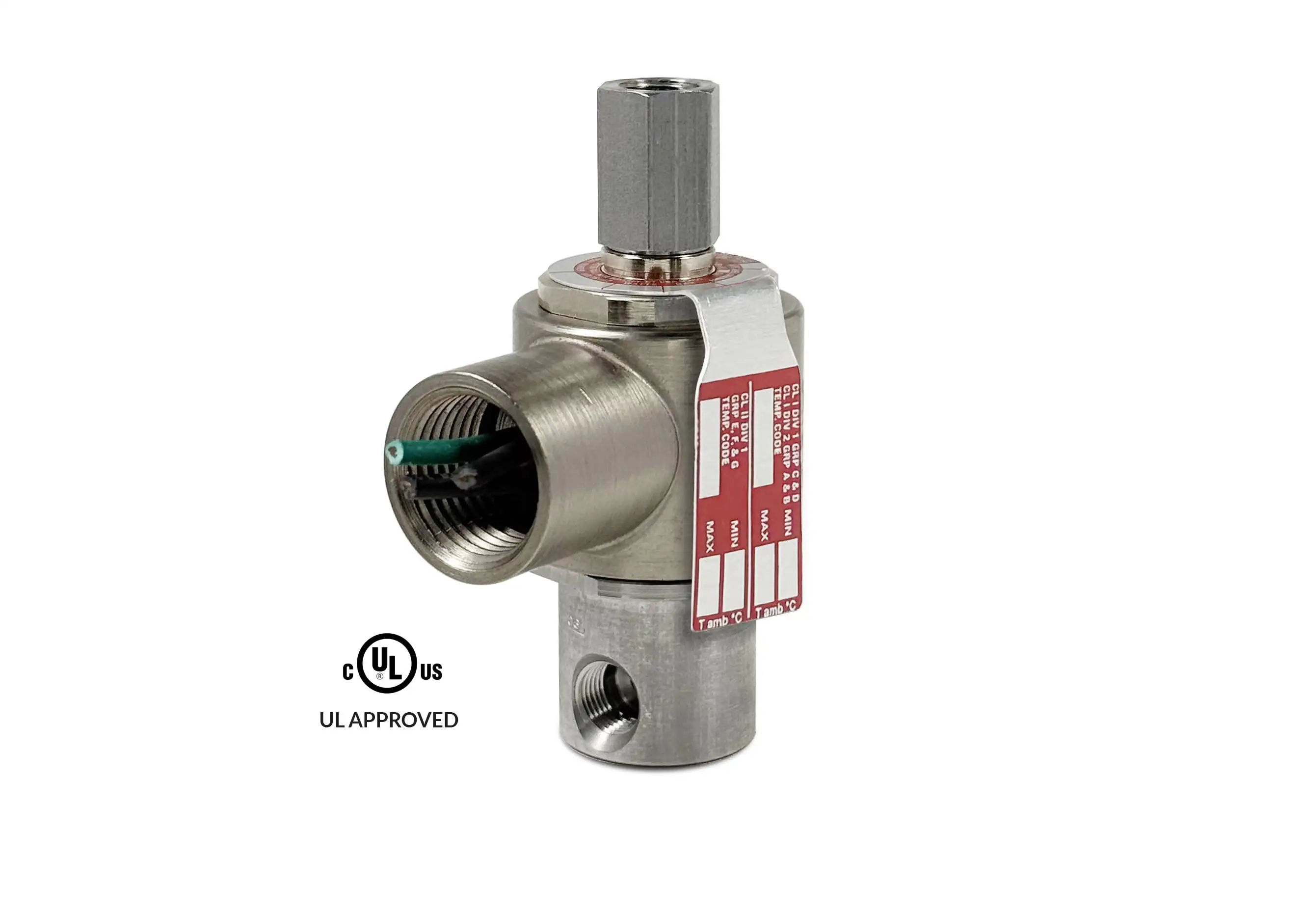
Series ELL50 Model ELL53 - Exhaust to Atmosphere

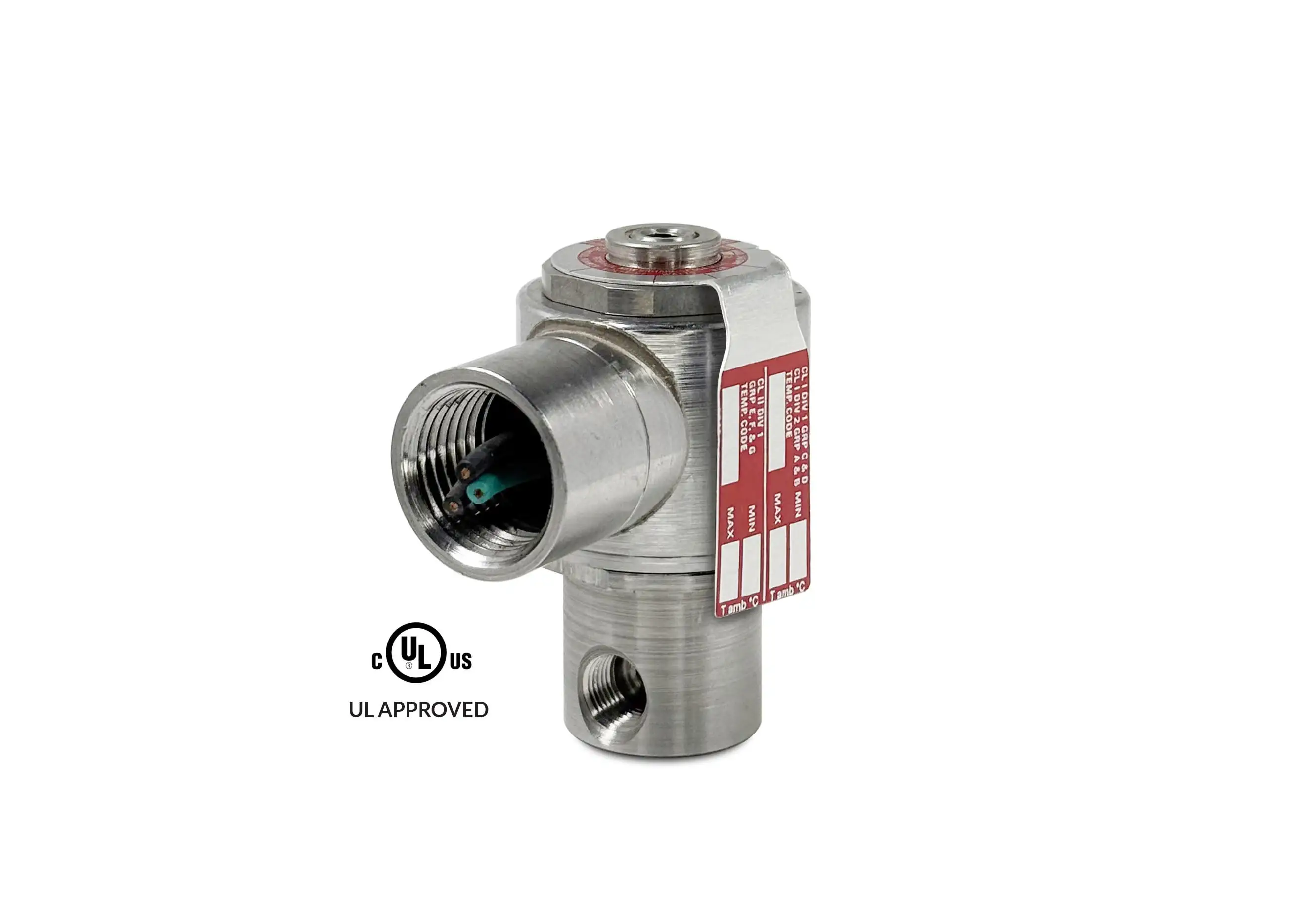
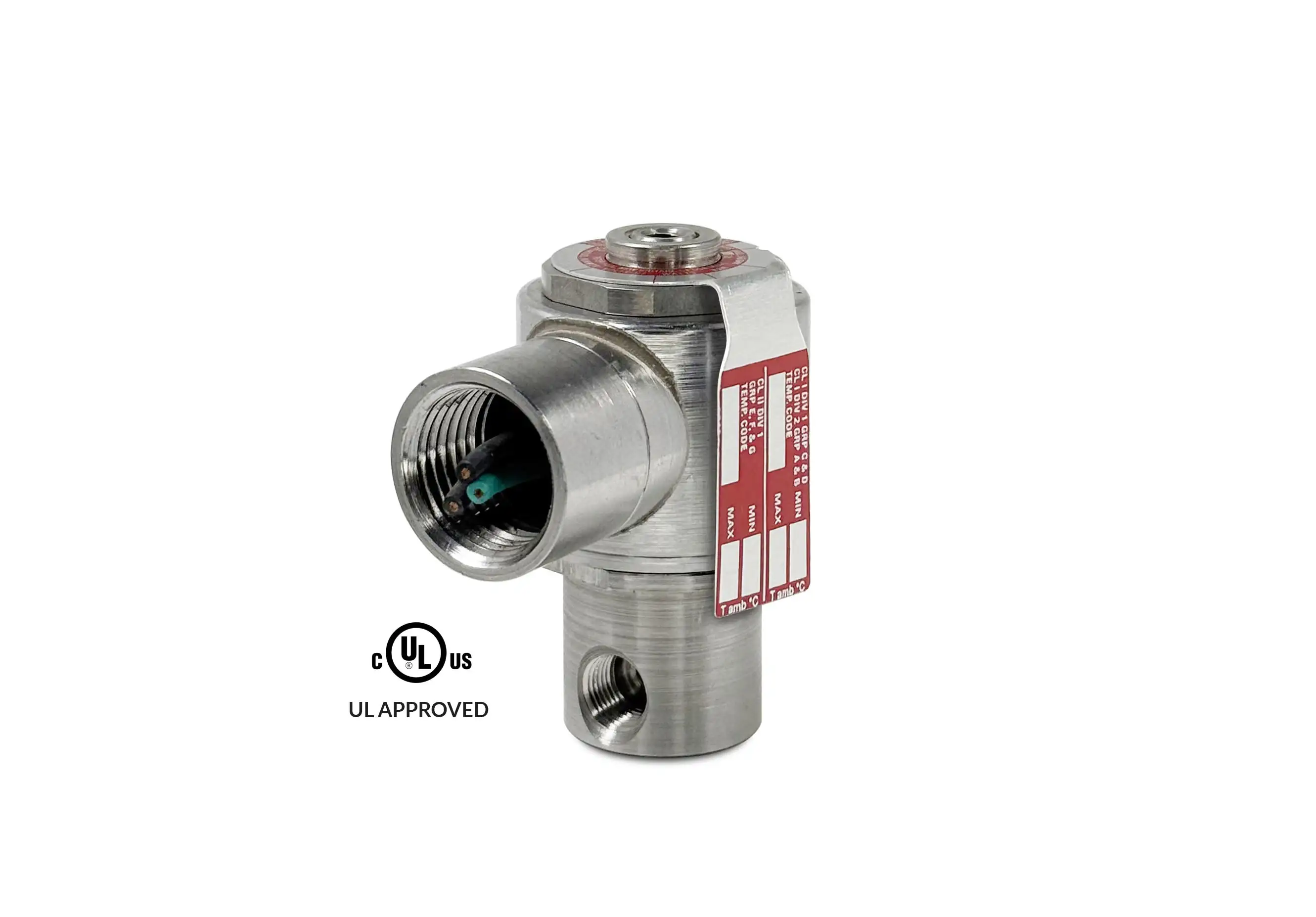
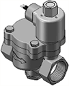
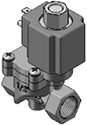
Series ELL50 Model ELL53 - Exhaust to Atmosphere valve
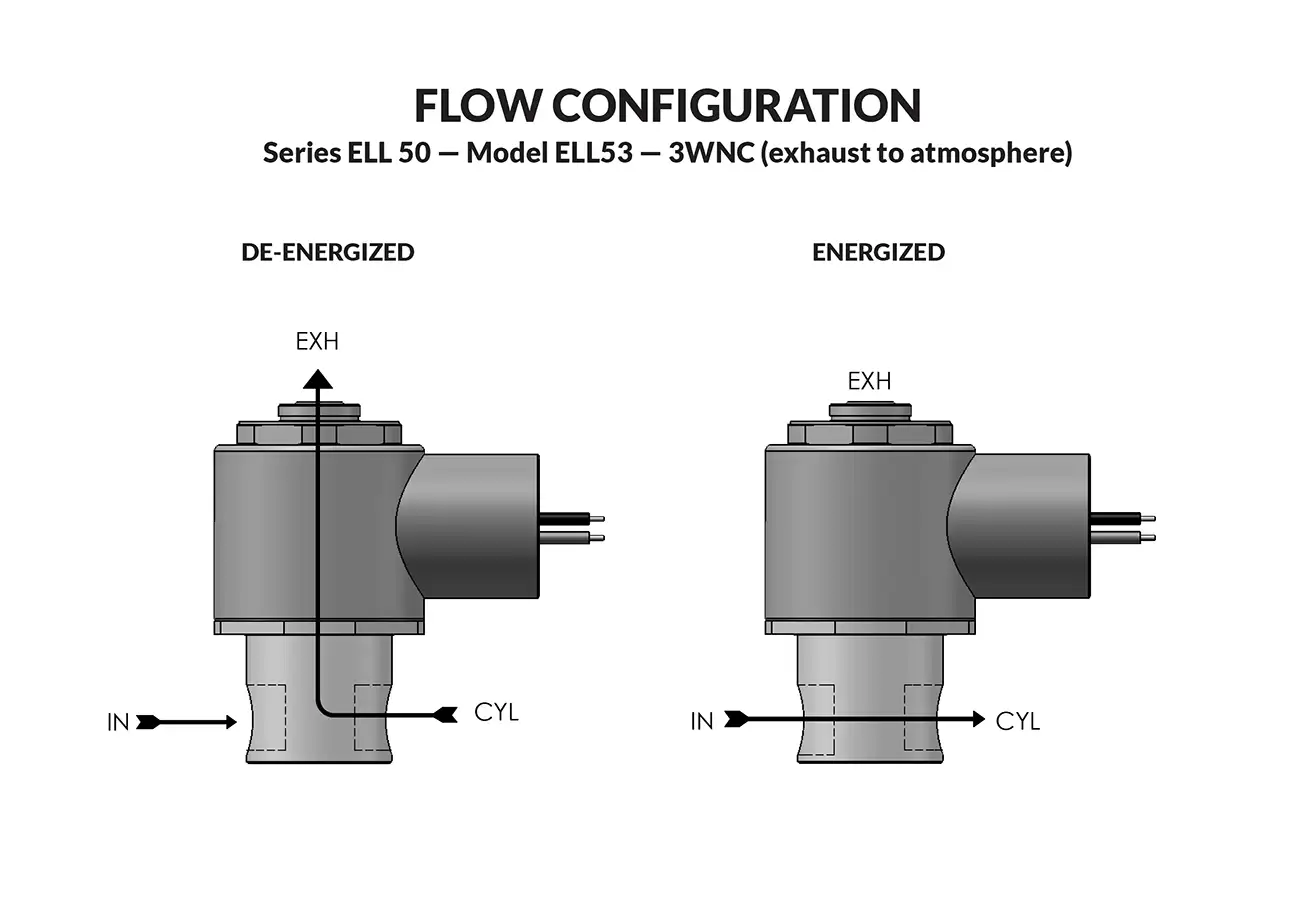
Series ELL50 Model ELL53 - Exhaust to Atmosphere flow diagram

PeterPaul explosion proof valves are used where fire or explosion hazards exist due to the presence of flammable gases or vapors, flammable liquids, combustible dust, or easily ignitable fibers. Hazardous Location valves are recommended, or in some cases compulsory, where a high level of protection from explosion is required.

  • Miniature Hazardous Location valves using even less power than an EL53.
  • Flame-proof construction.
  • High quality engineering.
Valve specifications — Series ELL50 Model ELL53 - Exhaust to Atmosphere
MAX. OPER. PRESS. DIFF.ORIFICE SIZECV FACTORNORTH AMERICAN
VALVE NUMBER
DCINLETEXHINLETEXH
1201/321/32.022.022ELL53GG8DCCM-∆

Ordering Information:

Seal Material: Replace ∆ with desired code - Blank = Nitrile (Buna) S = Low Temp Buna. N = FKM* E = Neoprene A = EPDM

When ordering valves or repair packs add voltage and frequency to complete valve number. For example: valve (ELL53GG8DCCM 12/DC) repair pack (5KELL53GGD DC)

When ordering operators add the letter “O” to the front of the valve number, replace body port number with the letter “D”: example: operator (OELL53GGDDCCM 12/DC)


Coil Voltage
12, 24/DC
Nominal Power
DC — .85 Watts
Coil Construction
Molded Class F with 3rd wire ground (Std.), Potted and Class H Option
Typical Response Time on Air
4 - 16 Milliseconds
Operating Speed
Up to 600 CPM
Duty Cycle
Continuous
Internal Components
Stainless Steel
Elastomers
Nitrile (Buna) (Std.). Many other elastomers available.*
Orifice Diameter
See table above.
Porting
1/8" NPT (Std.)
Housing
Flame-Proof construction with 1/2" NPT conduit
Listings
Valves are UL listed and CSA certified for Hazardous Locations — Class I, Div 1, Group C and D - Class II, Div 1, Groups E, F, and G: Div 2, Groups A, B, C, D, E, F, and G.
Life Expectancy
Millions of cycles, depending on application, lubrication, etc.
Valve Weight
0.65 lbs
Repair Packs
See table above.
Options
Alternate Port Locations, Metering, Alternate Elastomers and All Stainless Steel Construction*
Media
Air and other common gases only.*
Valve Temperature Range
Standard Valves – 0°F (-18°C) to 104°F (40°C) ambient; 0°F (-18°C) to 150°F (65°C) media. Optional Valves – can tolerate much higher or much lower ambient and media temperatures.*
Maximum Operating Pressure Differentials
See table above.
Burst Pressure
4000 PSI
Leakage
Bubble tight for standard valves.
Vacuum
To 5 Microns*

Series ELL50 Hazardous Location Valves

Technical drawing — MODEL ELL53 1/8-27 NPT 3WNC EXHAUST TO ATMOSPHERE EXPLOSION PROOF
MODEL ELL53
1/8-27 NPT
3WNC EXHAUST TO ATMOSPHERE EXPLOSION PROOF

Technical drawing — MODEL ELL53 10-32 BODY PORTS 3WNC EXHAUST TO ATMOSPHERE EXPLOSION PROOF
MODEL ELL53
10-32 BODY PORTS
3WNC EXHAUST TO ATMOSPHERE EXPLOSION PROOF

Technical drawing — MODEL ELL53 BODY OPTION "E" 3WNC EXHAUST TO ATMOSPHERE EXPLOSION PROOF
MODEL ELL53
BODY OPTION "E"
3WNC EXHAUST TO ATMOSPHERE EXPLOSION PROOF

Technical drawing — MODEL ELL53 BODY OPTION "O" 3WNC EXHAUST TO ATMOSPHERE EXPLOSION PROOF
MODEL ELL53
BODY OPTION "O"
3WNC EXHAUST TO ATMOSPHERE EXPLOSION PROOF

Technical drawing — MODEL ELL53 BODY OPTION "R" 3WNC EXHAUST TO ATMOSPHERE EXPLOSION PROOF
MODEL ELL53
BODY OPTION "R"
3WNC EXHAUST TO ATMOSPHERE EXPLOSION PROOF

Technical drawing — MODEL ELL53 METERED BODY 3WNC EXHAUST TO ATMOSPHERE EXPLOSION PROOF
MODEL ELL53
METERED BODY
3WNC EXHAUST TO ATMOSPHERE EXPLOSION PROOF

Minimum quantity required. Please contact sales for additional assistance.
sales@peterpaul.com
 
Stainless Steel (Std.)

Series 50 Operators Explosion Proof

Technical drawing — MODEL OELL53 3WNC EXHAUST TO ATMOSPHERE EXPLOSION PROOF
MODEL OELL53 3WNC EXHAUST TO ATMOSPHERE EXPLOSION PROOF
Certification
North American

Series EL50 Model EL53 - Exhaust to Atmosphere

Series EL50 Model EL53 - Exhaust to Atmosphere
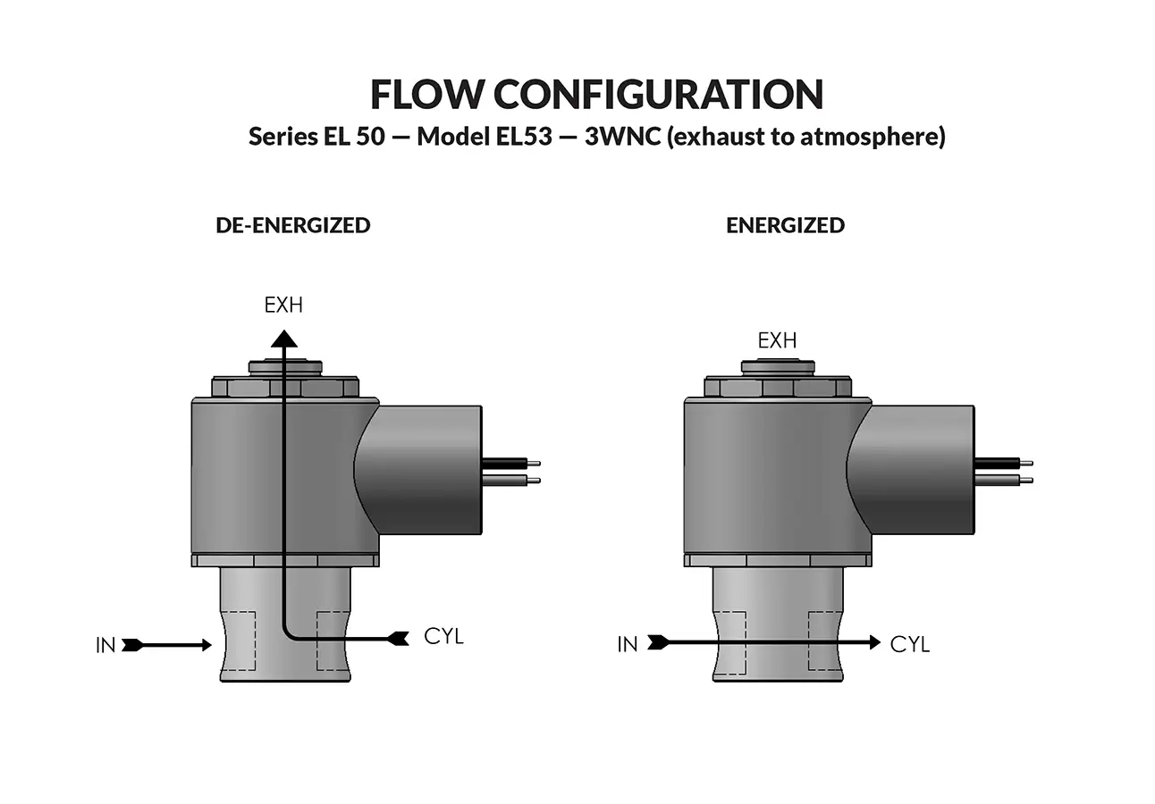
Series EL 50 Model EL53 - Exhaust to Atmosphere flow diagram

PeterPaul explosion proof valves are used where fire or explosion hazards exist due to the presence of flammable gases or vapors, flammable liquids, combustible dust, or easily ignitable fibers. Hazardous Location valves are recommended, or in some cases compulsory, where a high level of protection from explosion is required.

  • Miniature Hazardous Location valves using even less power than an E53.
  • Flame-proof construction.
  • High quality engineering.
Valve specifications — Series EL 50 Model EL53 - Exhaust to Atmosphere
MAX. OPER. PRESS. DIFF.ORIFICE SIZECV FACTORNORTH AMERICAN
VALVE NUMBER
ACDCINLETEXHINLETEXH
1201201/321/32.022.048EL53GG8DCCM-∆
1201201/323/64.055.048EL53GH8DCCM-∆
60603/643/64.055.048EL53HH8DCCM-∆
30301/161/16.075.075EL53JJ8DCCM-∆

Ordering Information:

Seal Material: Replace ∆ with desired code - Blank = Nitrile (Buna) S = Low Temp Buna. N = FKM* E = Neoprene A = EPDM

When ordering valves or repair packs add voltage and frequency to complete valve number. For example: valve (EL53HH8DCCM 120/60) repair pack (5KEL53HHD AC)

When ordering operators add the letter “O” to the front of the valve number, replace body port number with the letter “D”: example: operator (OEL53HHDDCCM 120/60)


Coil Voltage
12/DC, 24/DC, 48/DC, 125/DC, 120/60-110/50, 240/60, and 24/60.
Nominal Power
AC — 1.8 Watts, DC — 1.8 Watts
Coil Construction
Molded Class F with third wire ground (Std.), Class H or Potted (Opt.)
Typical Response Time on Air
4 - 16 Milliseconds
Operating Speed
Up to 600 CPM
Duty Cycle
Continuous
Internal Components
Stainless Steel. Copper – AC Only.
Elastomers
Nitrile (Buna) (Std.). Many other elastomers available.*
Orifice Diameter
See table above.
Porting
1/8" NPT (Std.)
Housing
Flame-Proof construction with 1/2" NPT conduit
Listings
Valves are UL listed and CSA certified for Hazardous Locations — Class I, Div 1, Group C and D - Class II, Div 1, Groups E, F, and G: Div 2, Groups A, B, C, D, E, F, and G.
Life Expectancy
Millions of cycles, depending on application, lubrication, etc.
Valve Weight
0.65 lbs
Repair Packs
See table above.
Options
Alternate Port Locations, Metering, Alternate Elastomers and All Stainless Steel Construction*
Media
Air and other common gases and common refrigerants except ammonia, city gas supplies by public utilities, Nos. 1 and 2 fuel oils, oils having viscosities not more than 40, SU at 100° F, steam, some hydraulic and water or other aqueous non-flammable liquid
Valve Temperature Range
Standard Valves – 0°F (-18°C) to 104°F (40°C) ambient; 0°F (-18°C) to 150°F (65°C) media. Optional Valves – can tolerate much higher or much lower ambient and media temperatures.*
Maximum Operating Pressure Differentials
See table above.
Burst Pressure
4000 PSI
Leakage
Bubble tight for standard valves.
Vacuum
To 5 Microns*

Series EL 50 Hazardous Location Valves

Technical drawing — MODEL EL53 1/8-27 NPT 3WNC EXHAUST TO ATMOSPHERE EXPLOSION PROOF
MODEL EL53
1/8-27 NPT
3WNC EXHAUST TO ATMOSPHERE EXPLOSION PROOF

Technical drawing — MODEL EL53 10-32 BODY PORTS 3WNC EXHAUST TO ATMOSPHERE EXPLOSION PROOF
MODEL EL53
10-32 BODY PORTS
3WNC EXHAUST TO ATMOSPHERE EXPLOSION PROOF

Technical drawing — MODEL EL53 BODY OPTION "E" 3WNC EXHAUST TO ATMOSPHERE EXPLOSION PROOF
MODEL EL53
BODY OPTION "E"
3WNC EXHAUST TO ATMOSPHERE EXPLOSION PROOF

Technical drawing — MODEL EL53 BODY OPTION "O" 3WNC EXHAUST TO ATMOSPHERE EXPLOSION PROOF
MODEL EL53
BODY OPTION "O"
3WNC EXHAUST TO ATMOSPHERE EXPLOSION PROOF

Technical drawing — MODEL EL53 BODY OPTION "R" 3WNC EXHAUST TO ATMOSPHERE EXPLOSION PROOF
MODEL EL53
BODY OPTION "R"
3WNC EXHAUST TO ATMOSPHERE EXPLOSION PROOF

Technical drawing — MODEL EL53 METERED BODY 3WNC EXHAUST TO ATMOSPHERE EXPLOSION PROOF
MODEL EL53
METERED BODY
3WNC EXHAUST TO ATMOSPHERE EXPLOSION PROOF

Minimum quantity required. Please contact sales for additional assistance.
sales@peterpaul.com
 
Stainless Steel (Std.)

Series 50 Operators Explosion Proof

Technical drawing — MODEL OEL53 3WNC EXHAUST TO ATMOSPHERE EXPLOSION PROOF
MODEL OEL53 3WNC EXHAUST TO ATMOSPHERE EXPLOSION PROOF
Certification
North American

Series L58 Model L583 - Exhaust to Atmosphere

Series L58 Model L583 - Exhaust to Atmosphere
Series L58 Model L583 - Exhaust to Atmosphere flow diagram

Easily interfaced with circuit boards and miniaturized components. The versatility is for connecting electronic signals to pneumatic outputs. The small size is ideal for stand-alone use with #10-32 ports or multiple valves mounted on one manifold. Air and other common gases; filtration recommended, 30 microns or less.

  • May be used to pilot larger valves.
  • Ideal for micro electronic production equipment.
  • Great for medical and chemical analytical applications.
  • Can operate directly from most programmable controllers.
  • High quality engineering.

VALVE SPECIFICATIONS

Valve specifications — Series L58 Model L583 - Exhaust to Atmosphere
MAX. OPER. PRESS. DIFF.ORIFICE SIZECV FACTORVALVE NUMBER
DCINLETEXHINLETEXH
1450.6 mm0.6 mm.010.010L583AA19DGM
1450.6 mm0.8 mm.010.020L583AF19DGM

Ordering Information:

When ordering valves or repair packs add voltage and frequency to complete valve number. For example: valve (L583AF19DGM 12/DC) repair pack (L583AF19DG DC)

When ordering operators add the letter “O” to the front of the valve number, replace body port number with the letter “D”: example: operator (OL583AFDDGM 12/DC)


Coil Voltage
12, 24/DC
Nominal Power
DC — 0.9 Watts
Coil Construction
Molded Class A with leadwires (Std.), Micro DIN (Opt.)
Typical Response Time on Air
DC - 9 Milliseconds
Operating Speed
Up to 600 CPM
Duty Cycle
Continuous
Internal Components
Stainless Steel
Elastomers
Nitrile (Buna) (Std.). Many other elastomers available.*
Orifice Diameter
See table above.
Porting
#10-32 and Manifold Mount
Life Expectancy
Millions of cycles, depending on application, lubrication, etc.
Valve Weight
0.13 lbs
Repair Packs
See table above.
Options
Round Stainless Steel, Male Stud Mount, and Manifold Mount*
Media
Air and other common gasses - filtration recommended - 30 microns or less.
Valve Temperature Range
Standard Valves – 5°F (-15°C) to 122°F (50°C) ambient and media. Note Do not allow water to freeze when using plastic body.
Maximum Operating Pressure Differentials
See table above.
Burst Pressure
1500 PSI
Leakage
Bubble tight for standard valves.
Vacuum
To 5 Microns*

Series L58 Model L583 Exhaust to Atmosphere Leads

Technical drawing — MODEL L583 3WNC EXHAUST TO ATMOSPHERE MOLDED COIL WITH LEADS MANIFOLD MOUNT PLASTIC BODY
MODEL L583 3WNC EXHAUST TO ATMOSPHERE MOLDED COIL WITH LEADS MANIFOLD MOUNT PLASTIC BODY
Technical drawing — MODEL L583 3WNC EXHAUST TO ATMOSPHERE MOLDED LEADS COIL STUD MANIFOLD MOUNT WITH STAINLESS STEEL BODY
MODEL L583 3WNC EXHAUST TO ATMOSPHERE MOLDED LEADS COIL STUD MANIFOLD MOUNT WITH STAINLESS STEEL BODY
Technical drawing — MODEL L583 3WNC EXHAUST TO ATMOSPHERE MOLDED LEAD STYLE COIL STAINLESS STEEL BODY WITH 10-32 PORTS
MODEL L583 3WNC EXHAUST TO ATMOSPHERE MOLDED LEAD STYLE COIL STAINLESS STEEL BODY WITH 10-32 PORTS
Technical drawing — MODEL L583 3WNC EXHAUST TO ATMOSPHERE MOLDED COIL WITH LEADS PLASTIC BODY WITH 10-32 PORTS
MODEL L583 3WNC EXHAUST TO ATMOSPHERE MOLDED COIL WITH LEADS PLASTIC BODY WITH 10-32 PORTS


Polyester Plastic (Std.), Stainless Steel (Opt.)

Series 58 Operators Molded Leads

Technical drawing — MODEL OL583 3WNC EXHAUST TO ATMOSPHERE MOLDED COIL WITH LEADS
MODEL OL583 3WNC EXHAUST TO ATMOSPHERE MOLDED COIL WITH LEADS

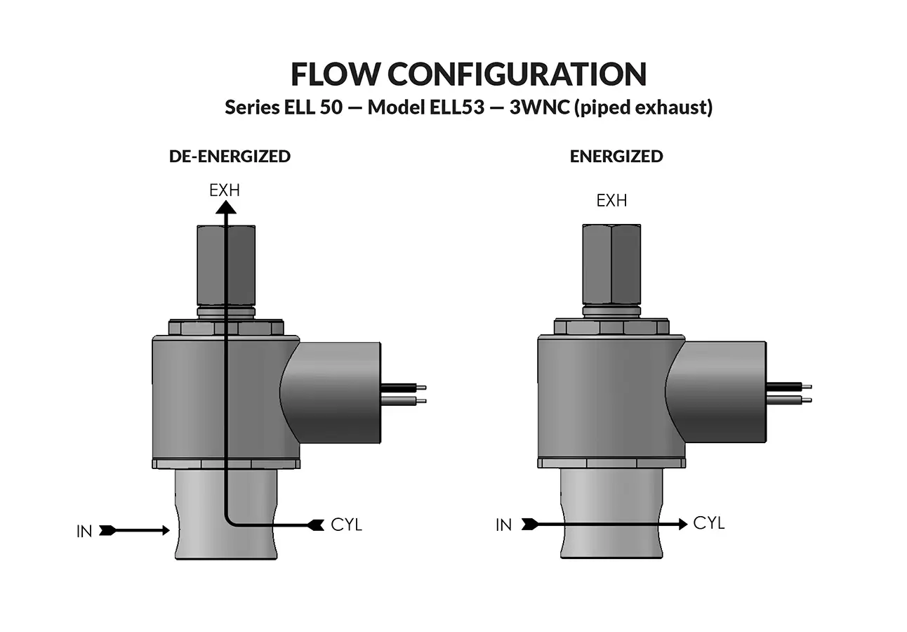
Series ELL50 Model ELL53 - Piped Exhaust

Series ELL50 Model ELL53 - Piped Exhaust
Series ELL50 Model ELL53 - Piped Exhaust flow diagram

PeterPaul explosion proof valves are used where fire or explosion hazards exist due to the presence of flammable gases or vapors, flammable liquids, combustible dust, or easily ignitable fibers. Hazardous Location valves are recommended, or in some cases compulsory, where a high level of protection from explosion is required.

  • Miniature Hazardous Location valves using even less power than an EL53.
  • Flame-proof construction.
  • High quality engineering.
Valve specifications — Series ELL50 Model ELL53 - Piped Exhaust
MAX. OPER. PRESS. DIFF.ORIFICE SIZECV FACTORNORTH AMERICAN
VALVE NUMBER
DCINLETEXHINLETEXH
1201/321/32.022.022ELL53GG8XCCM-∆

Ordering Information:

Seal Material: Replace ∆ with desired code - Blank = Nitrile (Buna) S = Low Temp Buna. N = FKM* E = Neoprene A = EPDM

When ordering valves or repair packs add voltage and frequency to complete valve number. For example: valve (ELL53GG8XCCM 12/DC) repair pack (5KELL53GGX DC)

When ordering operators add the letter “O” to the front of the valve number, replace body port number with the letter “D”: example: operator (OELL53GGDXCCM 12/DC)


Coil Voltage
12, 24/DC
Nominal Power
DC — .85 Watts
Coil Construction
Molded Class F with 3rd wire ground (Std.), Potted and Class H Option
Typical Response Time on Air
4 - 16 Milliseconds
Operating Speed
Up to 600 CPM
Duty Cycle
Continuous
Internal Components
Stainless Steel
Elastomers
Nitrile (Buna) (Std.). Many other elastomers available.*
Orifice Diameter
See table above.
Porting
1/8" NPT (Std.)
Housing
Flame-Proof construction with 1/2" NPT conduit
Listings
Valves are UL listed and CSA certified for Hazardous Locations — Class I, Div 1, Group C and D - Class II, Div 1, Groups E, F, and G: Div 2, Groups A, B, C, D, E, F, and G.
Life Expectancy
Millions of cycles, depending on application, lubrication, etc.
Valve Weight
0.65 lbs
Repair Packs
See table above.
Options
Alternate Port Locations, Metering, Alternate Elastomers and All Stainless Steel Construction*
Media
Air and other common gases only.*
Valve Temperature Range
Standard Valves – 0°F (-18°C) to 104°F (40°C) ambient; 0°F (-18°C) to 150°F (65°C) media. Optional Valves – can tolerate much higher or much lower ambient and media temperatures.*
Maximum Operating Pressure Differentials
See table above.
Burst Pressure
4000 PSI
Leakage
Bubble tight for standard valves.
Vacuum
To 5 Microns*

Series ELL50 Hazardous Location Valves

Technical drawing — MODEL ELL53 1/8-27 NPT 3WNC PIPED EXHAUST EXPLOSION PROOF
MODEL ELL53
1/8-27 NPT
3WNC PIPED EXHAUST EXPLOSION PROOF

Technical drawing — MODEL ELL53 10-32 PORTS 3WNC PIPED EXHAUST EXPLOSION PROOF
MODEL ELL53
10-32 PORTS
3WNC PIPED EXHAUST EXPLOSION PROOF

Technical drawing — MODEL ELL53 BODY OPTION "E" 3WNC PIPED EXHAUST EXPLOSION PROOF
MODEL ELL53
BODY OPTION "E"
3WNC PIPED EXHAUST EXPLOSION PROOF

Technical drawing — MODEL ELL53 BODY OPTION "O" 3WNC PIPED EXHAUST EXPLOSION PROOF
MODEL ELL53
BODY OPTION "O"
3WNC PIPED EXHAUST EXPLOSION PROOF

Technical drawing — MODEL ELL53 BODY OPTION "R" 3WNC PIPED EXHAUST EXPLOSION PROOF
MODEL ELL53
BODY OPTION "R"
3WNC PIPED EXHAUST EXPLOSION PROOF

Technical drawing — MODEL ELL53 METERED BODY 3WNC PIPED EXHAUST EXPLOSION PROOF
MODEL ELL53
METERED BODY
3WNC PIPED EXHAUST EXPLOSION PROOF

Minimum quantity required. Please contact sales for additional assistance. 
sales@peterpaul.com
Stainless Steel (Std.)

Series 50 Operators Explosion Proof

Technical drawing — MODEL OELL53 3WNC PIPED EXHAUST EXPLOSION PROOF
MODEL OELL53 3WNC PIPED EXHAUST EXPLOSION PROOF
Certification
North American
We will be closed

PeterPaul will be closed Monday, October 12th. We will re-open Tuesday, October 13th for regular business hours.  Please feel free to email us using the chat box below.