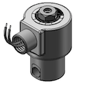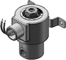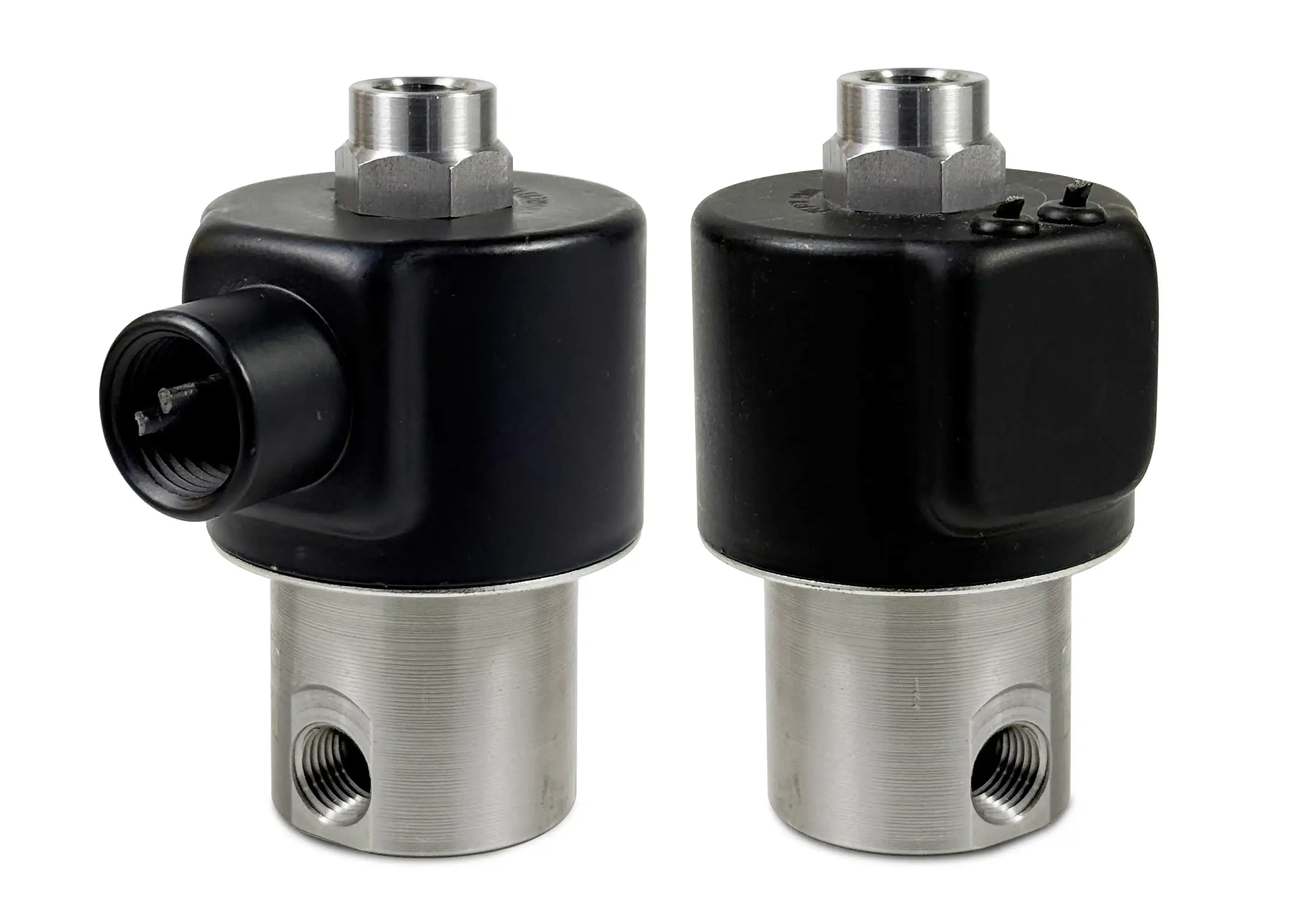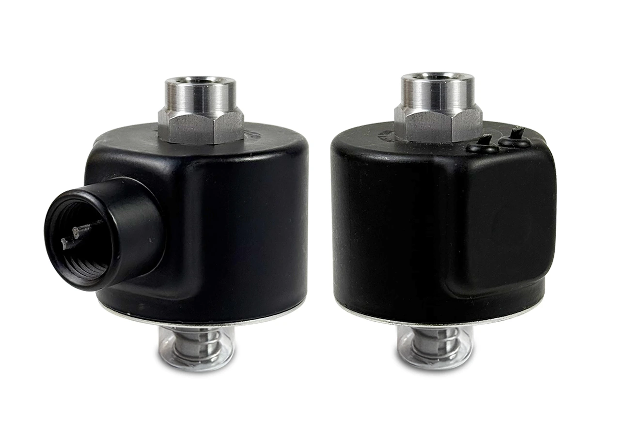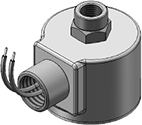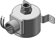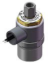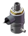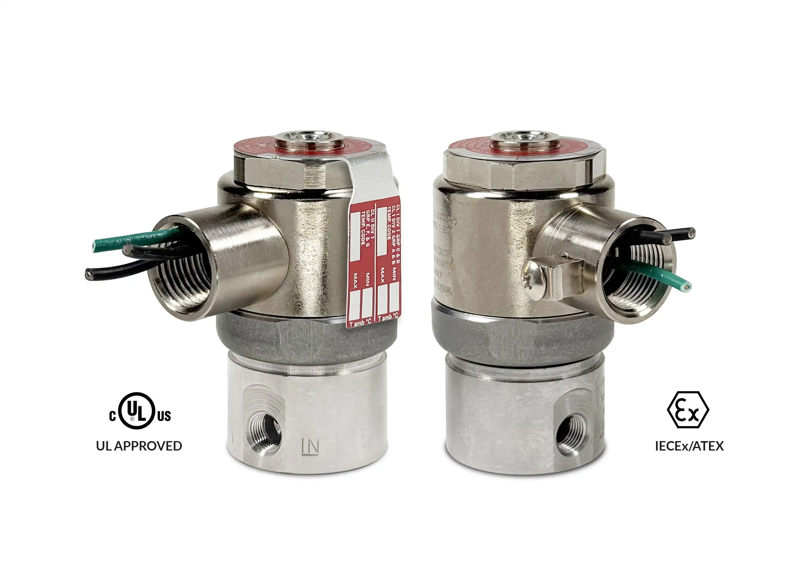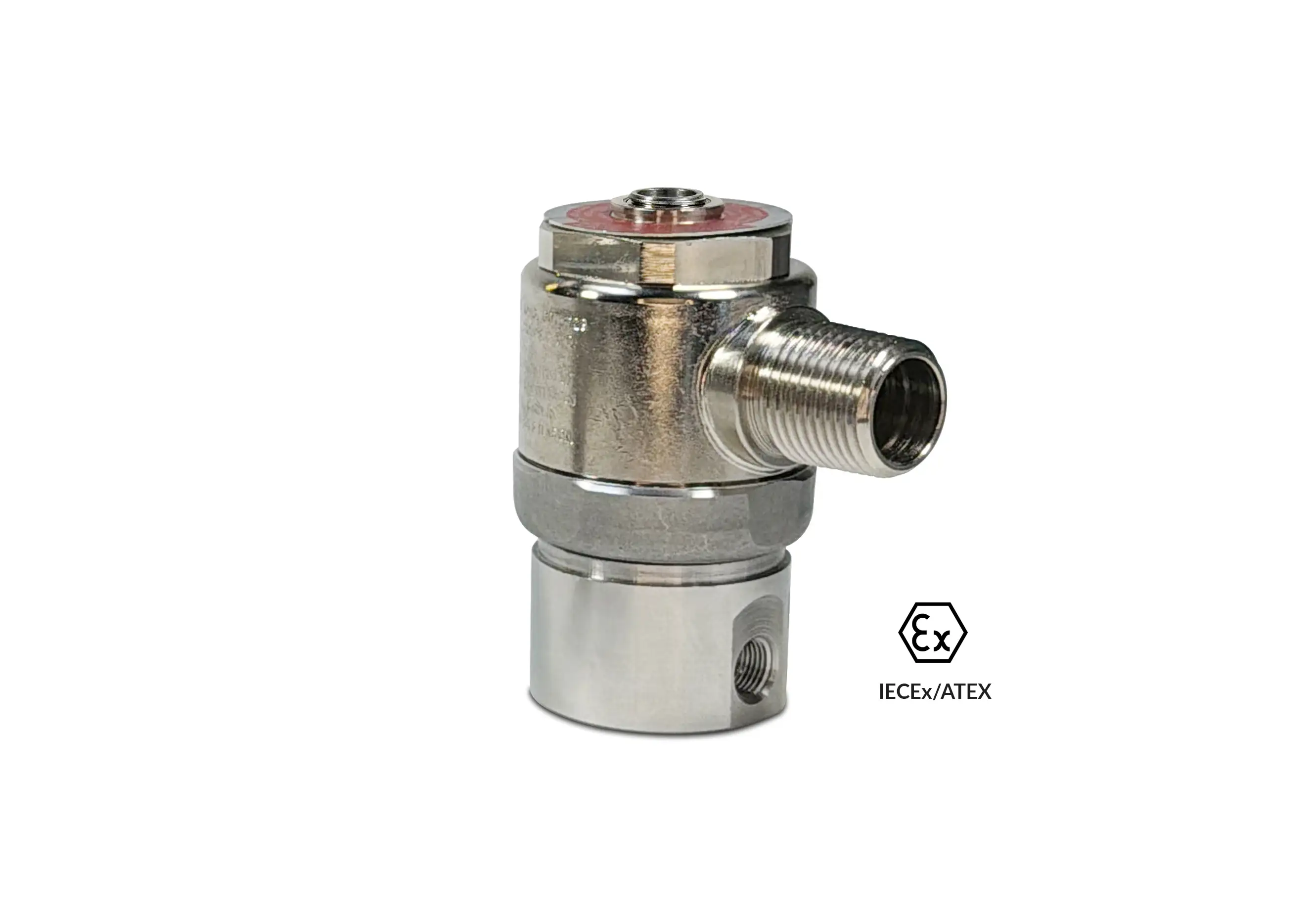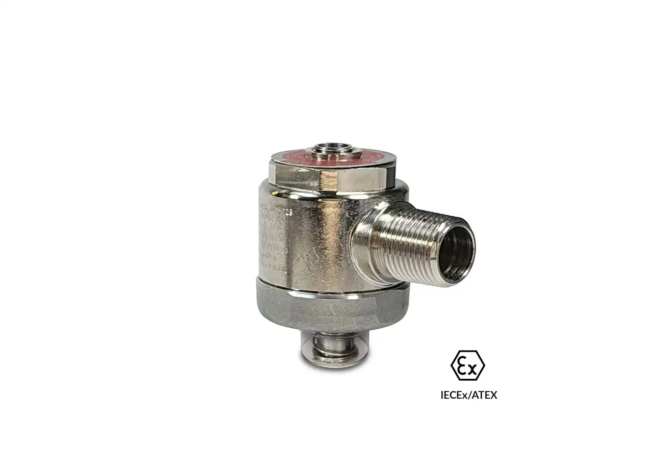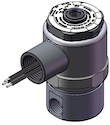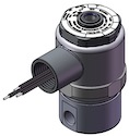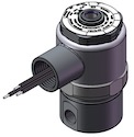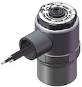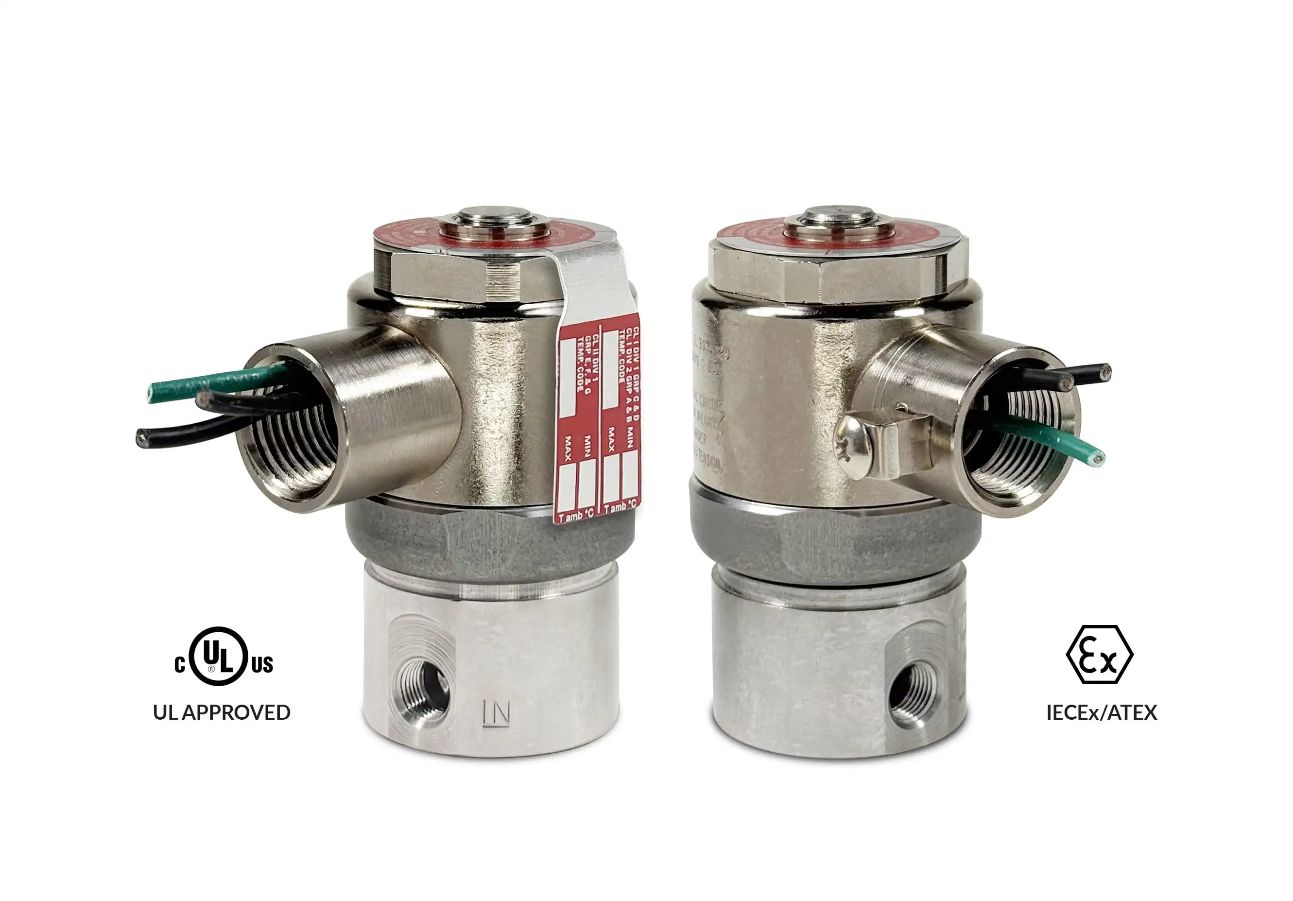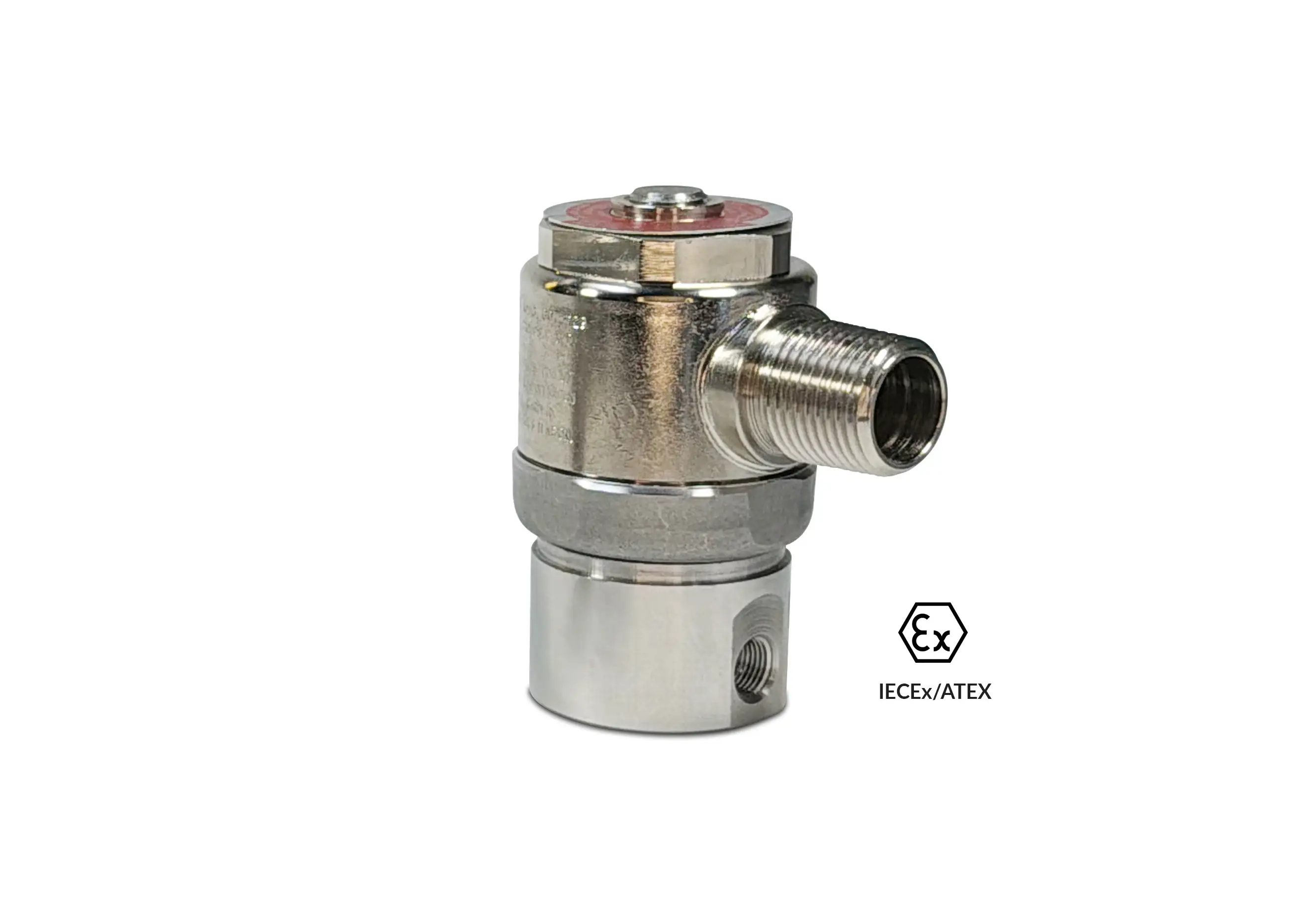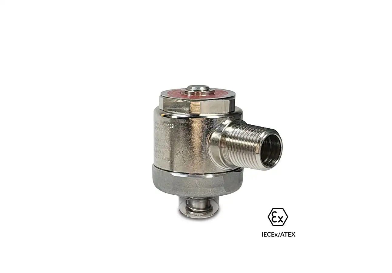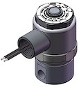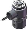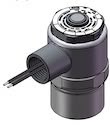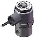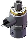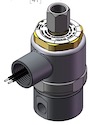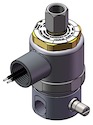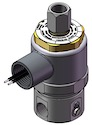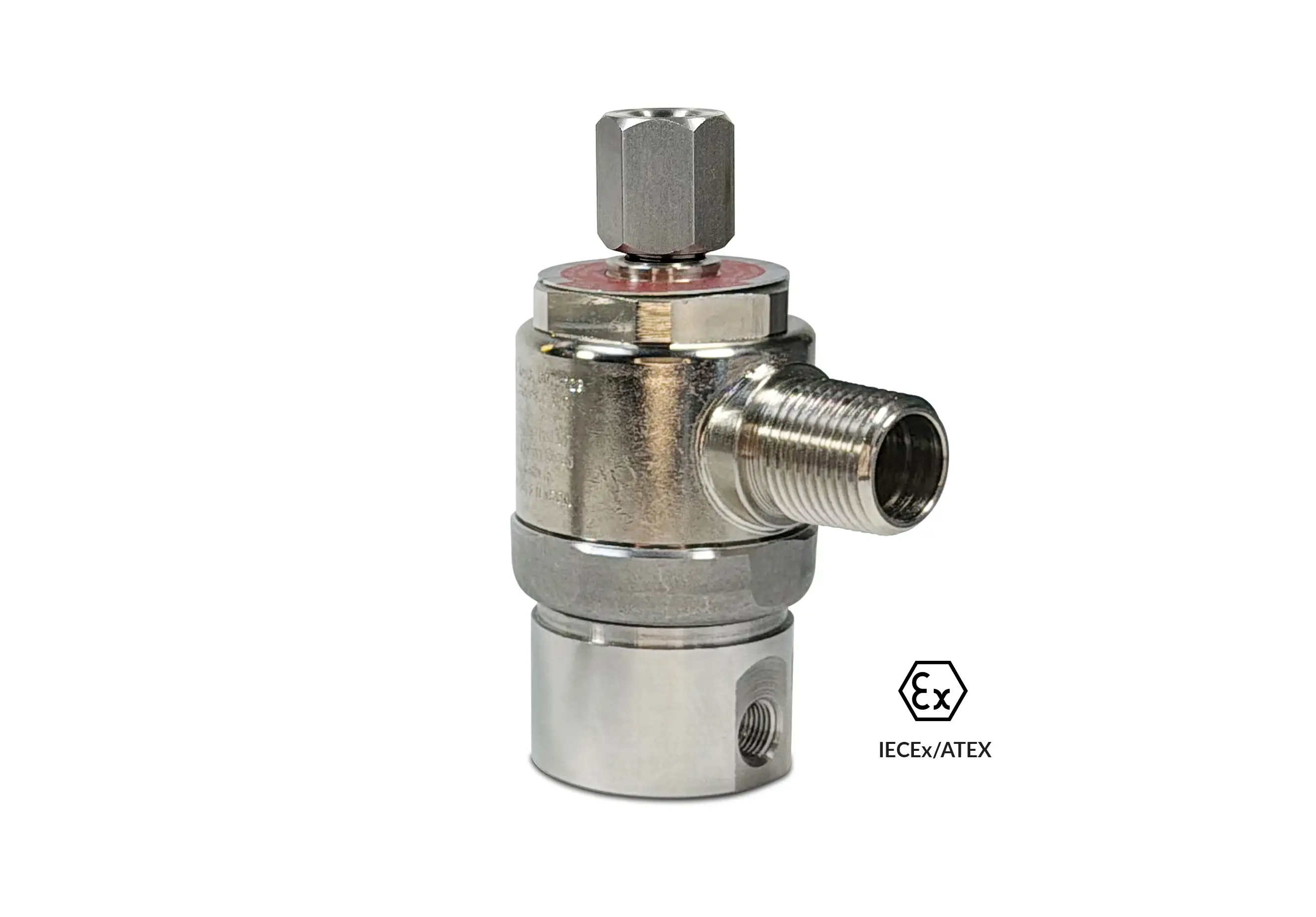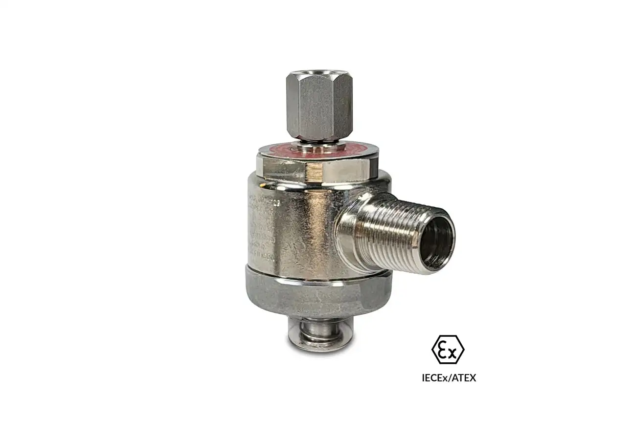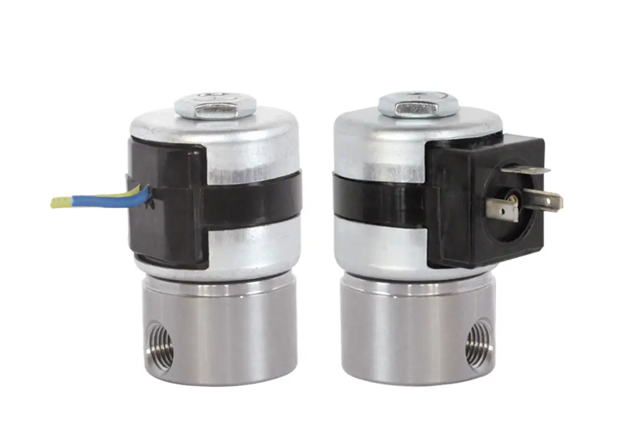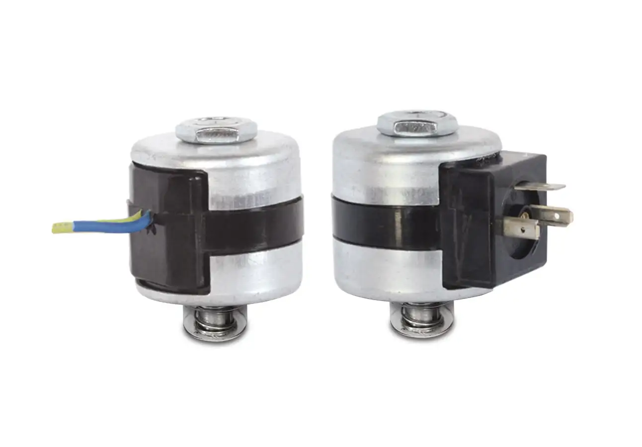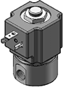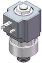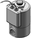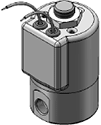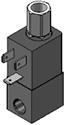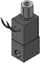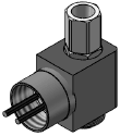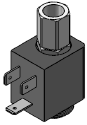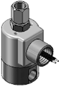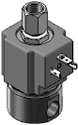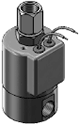
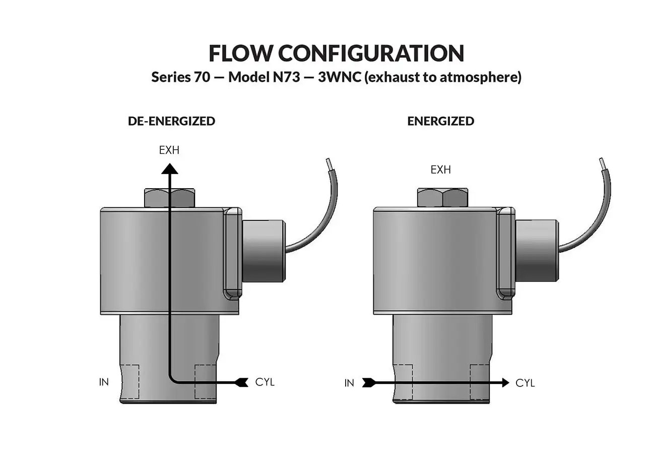
Series 70 Model N73 - Exhaust to Atmosphere

Series 70 Model N73 - Exhaust to Atmosphere
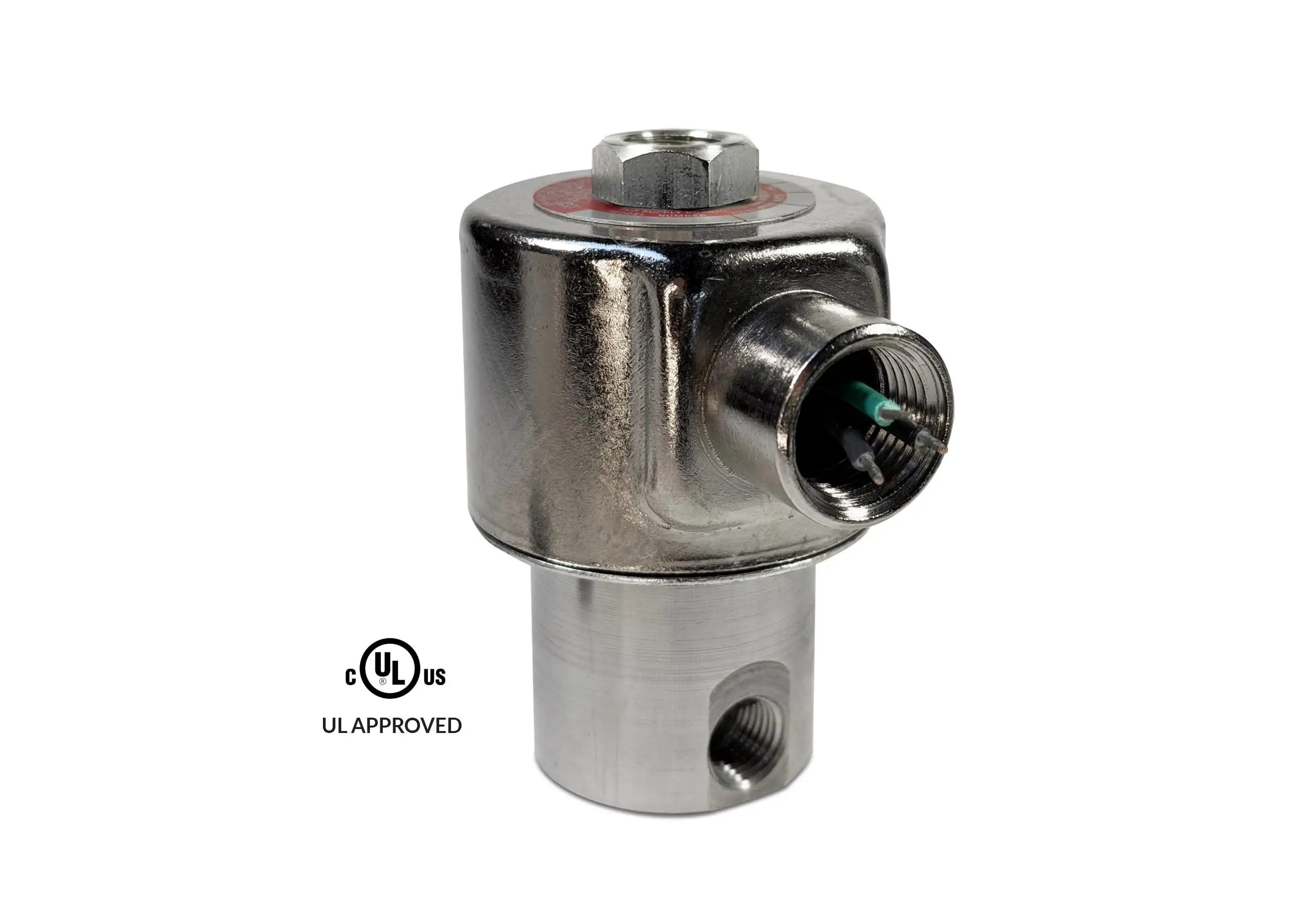
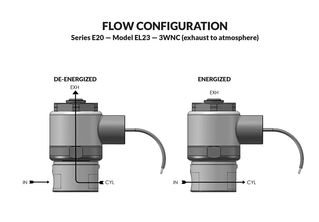
Series 70 Model N73 - Exhaust to Atmosphere flow diagram
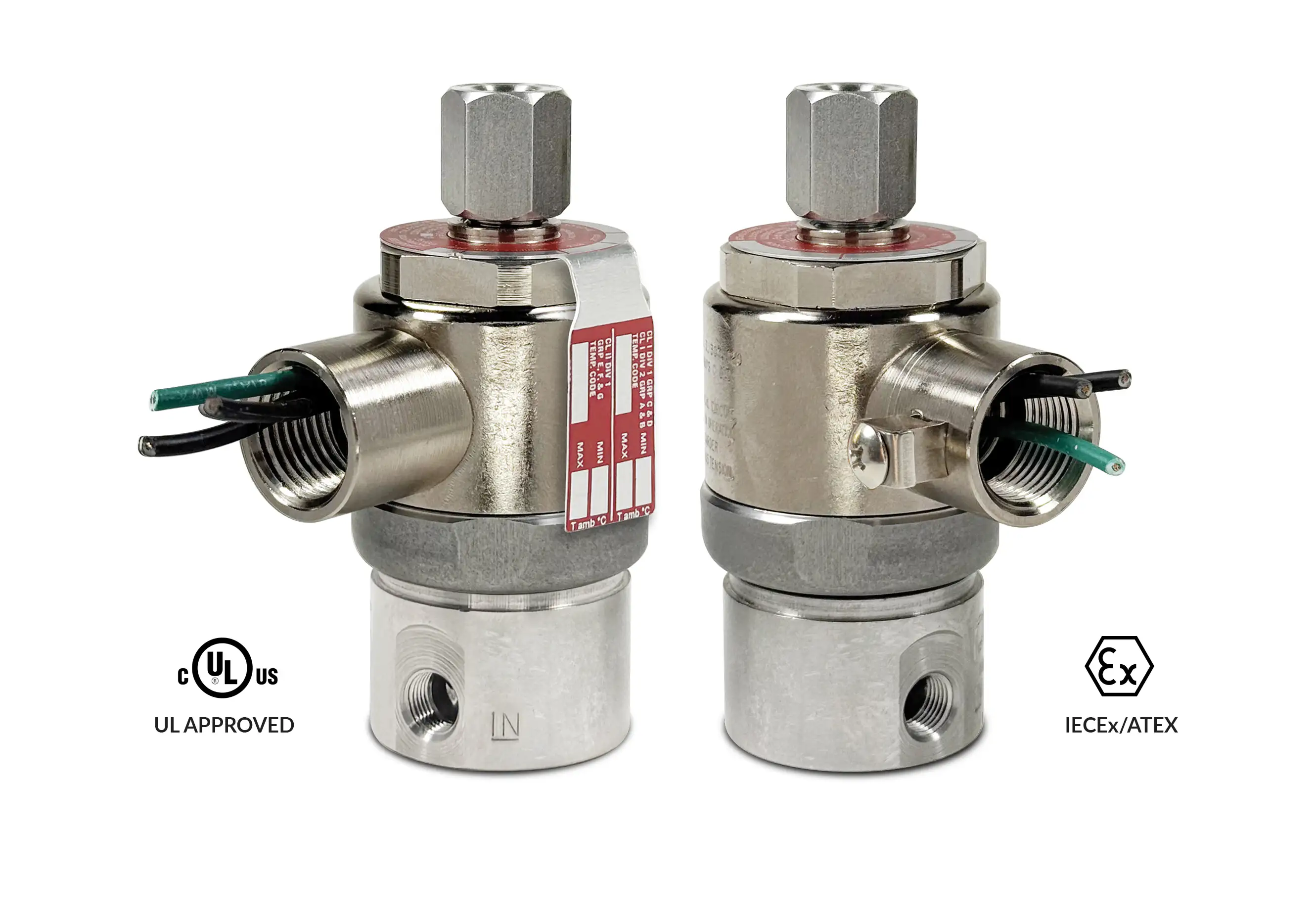
The N70 line PeterPaul Hazardous Location valves are UL listed and certified for non-incendive Hazardous Location Class 1, Div 2, Groups A, B, C and D; Class 2, Div 2, Groups E, F and G; T3C temperature rating.

  • Largest direct acting non-piloted valve we manufacture.
  • Large orifice.
  • High flow.
  • Will operate effectively at very low pressures or vacuum.
Valve specifications — Series 70 Model N73 - Exhaust to Atmosphere
MAX. OPER.
PRESS. DIFF.
ORIFICE SIZECV FACTORNORTH AMERICAN
VALVE NUMBER
CONDUIT HOUSING
1/4 NPT PORTS
ACDCINLETEXHINLETEXH
3503501/161/16.09.09N73JJ9DCP
2502503/323/32.22.22N73KK9DCP
1751751/81/8.35.35N73NN9DCP
1251255/325/32.45.45N73OO9DCP
1001003/163/16.50.50N73PP9DCP
50501/43/16.78.50N73RP9DCP

Ordering Information:

When ordering valves or repair packs add voltage and frequency to complete valve number. For example: valve (N73OO9DCP 120/60) repair pack (KN73OOD AC)

When ordering operators add the letter “O” to the front of the valve number, replace body port number with the letter “D”: example: operator (ON73OODDCP 120/60)


Coil Voltage
12/DC, 24/DC, 48/DC, 125/DC, 120/60-110/50, 240/60, and 24/60.
Nominal Power
AC — 18.0 Watts DC — 16.0 Watts
Coil Construction
Potted Class F or Class H (Opt.)
Typical Response Time on Air
4 - 16 Milliseconds
Operating Speed
Up to 600 CPM
Duty Cycle
Continuous
Internal Components
Stainless Steel. Copper – AC Only.
Elastomers
Nitrile (Buna) (Std.). Many other elastomers available.*
Orifice Diameter
See table above.
Porting
Standard 1/4" NPT (other ports available).*
Housing
1/2" NPT conduit *
Listings
Listed and Certified for Non-Incendive Hazardous Locations Class 1, Div 2, Groups A, B, C and D; Class 2, Div 2, Groups E, F and G; T3C Temperature rating.*
Life Expectancy
Millions of cycles, depending on application, lubrication, etc.
Valve Weight
Conduit Valve: 2.06 lb
Repair Packs
See table above.
Options
Alternate Port Locations, Metering and Alternate Elastomers * Consult representative or factory for options and specifications.
Media
Air, water, and other fluids compatible with standard Buna seals. Hot water, steam, gasoline, and many oils require special seal materials. (Series 70 pressure ratings may change due to the viscosity of the liquid.)*
Valve Temperature Range
Standard Valves – 0°F (-18°C) to 104°F (40°C) ambient; 0°F (-18°C) to 150°F (65°C) media. Optional Valves – can tolerate much higher or much lower ambient and media temperatures.*
Maximum Operating Pressure Differentials
See table above.
Burst Pressure
4000 PSI
Leakage
Bubble tight for standard valves.
Vacuum
To 5 Microns*

Series 70 HAZARDOUS LOCATION VALVES

Technical drawing — MODEL N73 1/4-18 NPT 3WNC CONDUIT CONNECTION
MODEL N73
1/4-18 NPT
3WNC CONDUIT CONNECTION

Technical drawing — MODEL N73 1/4-18 NPT 3WNC CONDUIT/BRACKET CONNECTION
MODEL N73
1/4-18 NPT
3WNC CONDUIT/BRACKET CONNECTION

Minimum quantity required. Please contact sales for additional assistance.
sales@peterpaul.com
Stainless Steel (Std.) or Brass (Opt.)
Certification
North American

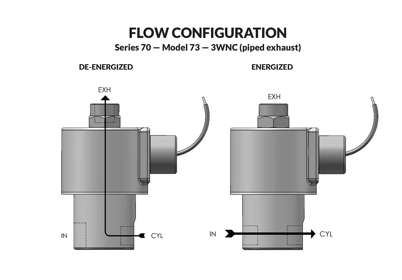
Series 70 Model 73 - Piped Exhaust

Series 70 Model 73 - Piped Exhaust
Series 70 Model 73 - Piped Exhaust solenoid operator
Series 70 Model 73 - Piped Exhaust flow diagram

Super valves that have ratings that formerly required valves of much greater size. Air, water, and other fluids are compatible with standard Buna seals. Hot water, steam, gasoline, and many oils require special seal materials.

  • Largest direct acting non-piloted valve we manufacture.
  • Large orifice.
  • High flow.
  • Will operate effectively at very low pressures or vacuum.
Valve specifications — Series 70 Model 73 - Piped Exhaust
MAX. OPER. PRESS. DIFF.ORIFICE SIZECV FACTORVALVE NUMBER
GROMMET HOUSING
VALVE NUMBER
CONDUIT HOUSING
ACDCINLETEXHINLETEXH1/4 NPT PORTS1/4 NPT PORTS
3503501/161/16.09.0973JJ9ZGM73JJ9ZCM
2502503/323/32.22.2273KK9ZGM73KK9ZCM
1751751/81/8.35.3573NN9ZGM73NN9ZCM
1251255/325/32.45.4573OO9ZGM73OO9ZCM
1001003/163/16.50.5073PP9ZGM73PP9ZCM
50501/43/16.78.5073RP9ZGM73RP9ZCM

Ordering Information:

When ordering valves or repair packs add voltage and frequency to complete valve number. For example: valve (73OO9ZGM 120/60) repair pack (K73OOX AC)

When ordering operators add the letter “O” to the front of the valve number, replace body port number with the letter “D”: example: operator (O73OODZGM 120/60)


Coil Voltage
12/DC, 24/DC, 48/DC, 125/DC, 120/60-110/50, 240/60, and 24/60.
Nominal Power
AC — 18.0 Watts DC — 16.0 Watts
Coil Construction
Molded Class F (Std.), Potted and Class H Option
Typical Response Time on Air
4 - 16 Milliseconds
Operating Speed
Up to 600 CPM
Duty Cycle
Continuous
Internal Components
Stainless Steel. Copper – AC Only.
Elastomers
Nitrile (Buna) (Std.). Many other elastomers available.*
Orifice Diameter
See table above.
Porting
Standard 1/4" NPT (other ports available).*`
Housing
Grommet and 1/2" NPT conduit - many options available.*
Listings
Most valves are UL and CSA listed.*
Life Expectancy
Millions of cycles, depending on application, lubrication, etc.
Valve Weight
Grommet Valve: 2.00 lb Conduit Valve: 2.06 lb
Repair Packs
See table above.
Options
Alternate Port Locations, Metering and Alternate Elastomers * Consult representative or factory for options and specifications.
Media
Air, water, and other fluids compatible with standard Buna seals. Hot water, steam, gasoline, and many oils require special seal materials. (Series 70 pressure ratings may change due to the viscosity of the liquid.)*
Valve Temperature Range
Standard Valves – 0°F (-18°C) to 104°F (40°C) ambient; 0°F (-18°C) to 150°F (65°C) media. Optional Valves – can tolerate much higher or much lower ambient and media temperatures.*
Maximum Operating Pressure Differentials
See table above.
Burst Pressure
4000 PSI
Leakage
Bubble tight for standard valves.
Vacuum
To 5 Microns*

Series 70 3WNC DIN PIPED EXHAUST

Technical drawing — MODEL 73 1/4-18 NPT 3WNC PIPED EXHAUST DIN STYLE COIL
MODEL 73
1/4-18 NPT
3WNC PIPED EXHAUST DIN STYLE COIL


SERIES 70 3WNC PIPED EXHAUST CONDUIT CONNECTION

Technical drawing — MODEL 73 1/4-18 NPT 3WNC CONDUIT CONNECTION
MODEL 73
1/4-18 NPT
3WNC CONDUIT CONNECTION


Series 70 General Purpose Valves Conduit/Bracket Connection

Technical drawing — MODEL 73 1/4-18 NPT 3WNC CONDUIT/BRACKET CONNECTION
MODEL 73
1/4-18 NPT
3WNC CONDUIT/BRACKET CONNECTION

Minimum quantity required. Please contact sales for additional assistance.
sales@peterpaul.com
 
Stainless Steel (Std.) or Brass (Opt.)

Series 70 Operators Conduit

Technical drawing — MODEL O73 3WNC PIPED EXHAUST CONDUIT CONNECTION
MODEL O73 3WNC PIPED EXHAUST CONDUIT CONNECTION

Series 70 Operators Conduit/Bracket Connection

Technical drawing — MODEL O73 3WNC PIPED EXHAUST CONDUIT/BRACKET CONNECTION
MODEL O73 3WNC PIPED EXHAUST CONDUIT/BRACKET CONNECTION

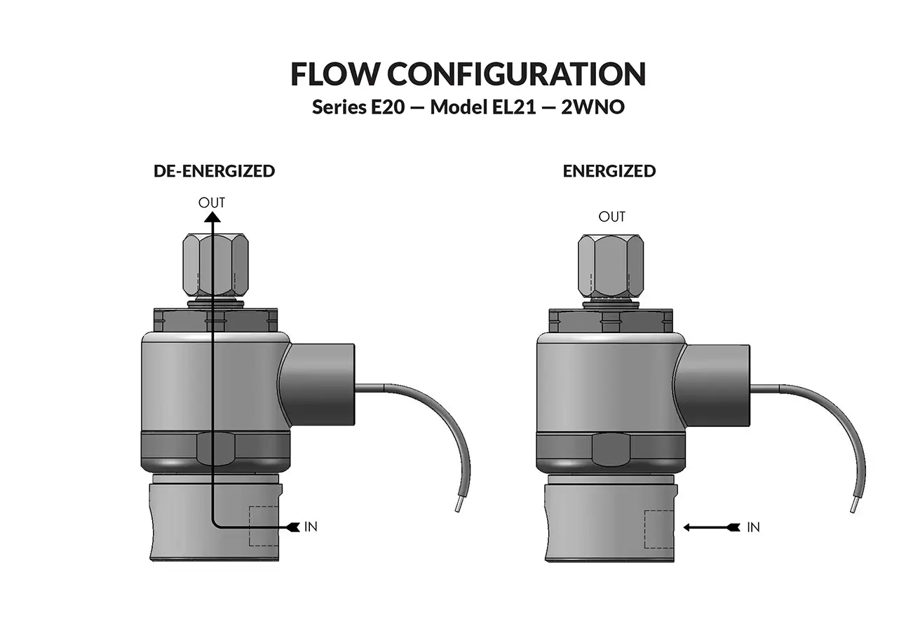
Series E20 Model EL21

Series E20 Model EL21
Series E20 Model EL21 flow diagram

PeterPaul explosion proof solenoid valves are used where fire or explosion hazards exist due to the presence of flammable gas or vapors, flammable liquids, combustible dust, or easily ignitable fibers. The low watt feature assures low power consumption, reducing drain on electrical systems. This is a benefit for renewable energy applications and where the solenoid valve must be on continuously.

  • Heavy duty and made of stainless steel.
  • A real workhorse with proven performance.
  • Low power consumption best for renewable energy and limited resource applications.
  • Wide range of orifice sizes from 1/32″ to 1/8″.
Valve specifications — Series 20 Model EL21
MAX. OPER. PRESS. DIFF.ORIFICE SIZECV FACTORNORTH AMERICAN
VALVE NUMBER
IECEx/ATEX
VALVE NUMBER
DC1/8 NPT PORTS1/4 NPT PORTS1/8 NPT PORTS1/4 NPT PORTS
4001/32.024EL21G7XCCP-∆EL21G9ZCCP-∆ELA21G7XCCP-∆ELA21G9ZCCP-∆
2203/64.053EL21H7XCCP-∆EL21H9ZCCP-∆ELA21H7XCCP-∆ELA21H9ZCCP-∆
1101/16.095EL21J7XCCP-∆EL21J9ZCCP-∆ELA21J7XCCP-∆ELA21J9ZCCP-∆
803/32.156EL21K7XCCP-∆EL21K9ZCCP-∆ELA21K7XCCP-∆ELA21K9ZCCP-∆
201/8.204EL21N7XCCP-∆EL21N9ZCCP-∆ELA21N7XCCP-∆ELA21N9ZCCP-∆

Ordering Information:

Seal Material: Replace ∆ with desired code - Blank = Nitrile (Buna) S = Low Temp Buna. N = FKM* E = Neoprene A = EPDM

When ordering valves or repair packs add voltage and frequency to complete valve number. For example: valve (EL21N7XCCP-N 24/DC) repair pack (2KEL21N-N DC)

When ordering operators add the letter “O” to the front of the valve number, and the body code will change. Contact the factory for the complete part number.


Coil Voltage
12, 24/DC
Nominal Power
1.8 Watts
Coil Construction
Potted Class F coil with 36” black lead wires and 36” green ground wire.
Typical Response Time on Air
4 - 16 Milliseconds
Operating Speed
Up to 600 CPM
Duty Cycle
Continuous
Internal Components
Stainless Steel
Elastomers
Buna, Fluorocarbon (FKM), Low Temperature Buna, EPDM or Neoprene.
Orifice Diameter
See table above.
Porting
1/8” OR 1/4” NPT
Housing
Flame-Proof construction with 1/2" NPT conduit
Listings
Valves are cULus listed for Hazardous Locations. — Class I, Div 1, Group C and D – Class II, Div 1, Group E, F, and G; Div 2 Groups A, B, C, D, E, F, and G.
Life Expectancy
Millions of cycles, depending on application, lubrication, etc.
Valve Weight
1.38 lbs
Repair Packs
See table above.
Options
Alternate Port Locations, Metering, Manual Override, Alternate Elastomers, Female DIN Style Connector Part Numbers DIN COIL (2 TERMINALS W/GROUND) #20-198 & DIN COIL (3 TERMINALS W/GROUND) #20-19102*
Media
Air, water, and other fluids are compatible with standard Buna seals. Hot water, steam, gasoline, and many oils require other seal materials. (Series 20 pressure ratings may change due to the viscosity of the liquid.)*
Valve Temperature Range
-22°F(-30°C) to 140°F (60°C) Exception: FKM is -4°F (-20°C) to 140°F (60°C).
Maximum Operating Pressure Differentials
See table above.
Burst Pressure
5,000 PSI
Leakage
Bubble tight for standard valves.
Vacuum
To 5 Microns*

Series 20 HAZARDOUS LOCATION VALVES

Technical drawing — MODEL EL21 1/4-18 NPT 2WNO EXPLOSION PROOF
MODEL EL21
1/4-18 NPT
2WNO EXPLOSION PROOF
Technical drawing — MODEL EL21 1/8-27 NPT 2WNO EXPLOSION PROOF
MODEL EL21
1/8-27 NPT
2WNO EXPLOSION PROOF
Technical drawing — MODEL EL21 BODY OPTION "O" 2WNO EXPLOSION PROOF
MODEL EL21
BODY OPTION "O"
2WNO EXPLOSION PROOF
Technical drawing — MODEL EL21 MANUAL OVERRIDE 2WNO EXPLOSION PROOF
MODEL EL21
MANUAL OVERRIDE
2WNO EXPLOSION PROOF
 
Stainless Steel (Std.)
Certification
North American
IECEx/ATEX
IECEx/ATEX Nomenclature

Coming soon.

Series E20 Model EL23 - Exhaust to Atmosphere

Series E20 Model EL23 - Exhaust to Atmosphere
Series E20 Model EL23 - Exhaust to Atmosphere Male Connector
Series E20 Model EL23 - Exhaust to Atmosphere solenoid operator
Series E20 Model EL23 - Exhaust to Atmosphere flow diagram

PeterPaul explosion-proof solenoid valves are used where fire or explosion hazards exist due to the presence of flammable gas or vapors, flammable liquids, combustible dust, or easily ignitable fibers. The low-watt feature assures low power consumption, reducing drain on electrical systems. This is a benefit for renewable energy applications and where the solenoid valve must be on continuously.

  • Heavy-duty and made of stainless steel.
  • A real workhorse with proven performance.
  • Low power consumption — best for renewable energy and limited-resource applications.
  • Wide range of orifice sizes, from 1/32″ to 1/8″.
Valve specifications — Series 20 Model EL23 - Exhaust to Atmosphere
MAX. OPER. PRESS. DIFF.ORIFICE SIZECV FACTORNORTH AMERICAN
VALVE NUMBER
IECEx/ATEX
VALVE NUMBER
DCINLETEXHINLETEXH1/8 NPT PORTS1/4 NPT PORTS1/8 NPT PORTS1/4 NPT PORTS
*3751/321/32.024.024EL23GG7DCCP-∆EL23GG9DCCP-∆ELA23GG7DCCP-∆ELA23GG9DCCP-∆
1503/643/64.052.052EL23HH7DCCP-∆EL23HH9DCCP-∆ELA23HH7DCCP-∆ELA23HH9DCCP-∆
1503/641/16.052.095EL23HJ7DCCP-∆EL23HJ9DCCP-∆ELA23HJ7DCCP-∆ELA23HJ9DCCP-∆
1001/161/16.095.095EL23JJ7DCCP-∆EL23JJ9DCCP-∆ELA23JJ7DCCP-∆ELA23JJ9DCCP-∆
1001/163/32.095.156EL23JK7DCCP-∆EL23JK9DCCP-∆ELA23JK7DCCP-∆ELA23JK9DCCP-∆
503/323/32.284.156EL23KK7DCCP-∆EL23KK9DCCP-∆ELA23KK7DCCP-∆ELA23KK9DCCP-∆
351/83/32.284.156EL23NK7DCCP-∆EL23NK9DCCP-∆ELA23NK7DCCP-∆ELA23NK9DCCP-∆
201/81/8.284.201EL23NN7DCCP-∆EL23NN9DCCP-∆ELA23NN7DCCP-∆ELA23NN9DCCP-∆

Ordering Information:

* Rating may vary based on an elastomer choice.

Seal Material: Replace ∆ with desired code - Blank = Nitrile (Buna) S = Low Temp Buna. N = FKM* E = Neoprene A = EPDM

When ordering valves or repair packs add voltage and frequency to complete valve number. For example: valve (EL23NN9DCCP-N 24/DC) repair pack (2KEL23KKD-N DC)

When ordering operators add the letter “O” to the front of the valve number, and the body code will change. Contact the factory for the complete part number.


Coil Voltage
12, 24/DC
Nominal Power
1.8 Watts
Coil Construction
Potted Class F coil with 36” black lead wires and 36” green ground wire.
Typical Response Time on Air
4 – 16 Milliseconds
Operating Speed
Up to 600 CPM
Duty Cycle
Continuous
Internal Components
Stainless Steel
Elastomers
Buna, Fluorocarbon (FKM), Low Temperature Buna, EPDM or Neoprene.
Orifice Diameter
See table above.
Porting
1/8” OR 1/4” NPT
Housing
Flame-Proof construction with 1/2" NPT conduit
Listings
Valves are cULus listed for Hazardous Locations. — Class I, Div 1, Group C and D – Class II, Div 1, Group E, F, and G; Div 2 Groups A, B, C, D, E, F, and G.
Life Expectancy
Millions of cycles, depending on application, lubrication, etc.
Valve Weight
1.38 lbs
Repair Packs
See table above.
Options
Alternate Port Locations, Metering, Manual Override, Alternate Elastomers, Female DIN Style Connector Part Numbers DIN COIL (2 TERMINALS W/GROUND) #20-198 & DIN COIL (3 TERMINALS W/GROUND) #20-19102*
Media
Air, water, and other fluids are compatible with standard Buna seals. Hot water, steam, gasoline, and many oils require other seal materials. (Series 20 pressure ratings may change due to the viscosity of the liquid.)*
Valve Temperature Range
-22°F(-30°C) to 140°F (60°C) Exception: FKM is -4°F (-20°C) to 140°F (60°C).
Maximum Operating Pressure Differentials
See table above.
Burst Pressure
5,000 PSI
Leakage
Bubble tight for standard valves.
Vacuum
To 5 Microns*

Series 20 HAZARDOUS LOCATION VALVES

Technical drawing — MODEL EL23 1/4-18 NPT 3WNC EXHAUST TO ATMOSPHERE EXPLOSION PROOF
MODEL EL23
1/4-18 NPT
3WNC EXHAUST TO ATMOSPHERE EXPLOSION PROOF
Technical drawing — MODEL EL23 1/8-27 NPT 3WNC EXHAUST TO ATMOSPHERE EXPLOSION PROOF
MODEL EL23
1/8-27 NPT
3WNC EXHAUST TO ATMOSPHERE EXPLOSION PROOF
Technical drawing — MODEL EL23 BODY OPTION "O" 3WNC EXHAUST TO ATMOSPHERE EXPLOSION PROOF
MODEL EL23
BODY OPTION "O"
3WNC EXHAUST TO ATMOSPHERE EXPLOSION PROOF
Technical drawing — MODEL EL23 BODY OPTION "E" 3WNC EXHAUST TO ATMOSPHERE EXPLOSION PROOF
MODEL EL23
BODY OPTION "E"
3WNC EXHAUST TO ATMOSPHERE EXPLOSION PROOF
Technical drawing — MODEL EL23 BODY OPTION "R" 3WNC EXHAUST TO ATMOSPHERE EXPLOSION PROOF
MODEL EL23
BODY OPTION "R"
3WNC EXHAUST TO ATMOSPHERE EXPLOSION PROOF
Technical drawing — MODEL EL23 MANUAL OVERRIDE 3WNC EXHAUST TO ATMOSPHERE EXPLOSION PROOF
MODEL EL23
MANUAL OVERRIDE
3WNC EXHAUST TO ATMOSPHERE EXPLOSION PROOF
Technical drawing — MODEL EL23 METERING 3WNC EXHAUST TO ATMOSPHERE EXPLOSION PROOF
MODEL EL23
METERING
3WNC EXHAUST TO ATMOSPHERE EXPLOSION PROOF
Minimum quantity required. Please contact sales for additional assistance.
sales@peterpaul.com
 
Stainless Steel (Std.)
Certification
North American
IECEx/ATEX
IECEx/ATEX Nomenclature

Coming soon.

Series E20 Model EL22

Series E20 Model EL22
Series E20 Model EL22 Male Connector
Series E20 Model EL22 solenoid operator
Series E20 Model EL22 flow diagram

PeterPaul explosion proof solenoid valves are used where fire or explosion hazards exist due to the presence of flammable gas or vapors, flammable liquids, combustible dust or easily ignitable fibers. The low watt feature assures low power consumption reducing drain on electrical systems. This is a benefit for renewable energy applications and where the solenoid valve must be on continuously.

  • Heavy duty and made of stainless steel.
  • A real workhorse with proven performance.
  • Low power consumption best for renewable energy and limited resource applications.
  • Wide range of orifice sizes from 1/32″ to 1/8″.
Valve specifications — Series 20 Model EL22
MAX. OPER. PRESS. DIFF.ORIFICE SIZECV FACTORNORTH AMERICAN
VALVE NUMBER
IECEx/ATEX
VALVE NUMBER
DC1/8 NPT PORTS1/4 NPT PORTS1/8 NPT PORTS1/4 NPT PORTS
5001/32.024EL22G7DCCP-∆EL22G9DCCP-∆ELA22G7DCCP-∆ELA22G9DCCP-∆
2503/64.052EL22H7DCCP-∆EL22H9DCCP-∆ELA22H7DCCP-∆ELA22H9DCCP-∆
1251/16.095EL22J7DCCP-∆EL22J9DCCP-∆ELA22J7DCCP-∆ELA22J9DCCP-∆
753/32.156EL22K7DCCP-∆EL22K9DCCP-∆ELA22K7DCCP-∆ELA22K9DCCP-∆
501/8.284EL22N7DCCP-∆EL22N9DCCP-∆ELA22N7DCCP-∆ELA22N9DCCP-∆

Ordering Information:

Seal Material: Replace ∆ with desired code - Blank = Nitrile (Buna) S = Low Temp Buna. N = FKM* E = Neoprene A = EPDM

When ordering valves or repair packs add voltage and frequency to complete valve number. For example: valve (EL22N7DCCP-N 24/DC) repair pack (2KEL22N-N DC)

When ordering operators add the letter “O” to the front of the valve number, and the body code will change. Contact the factory for the complete part number.


Coil Voltage
12, 24/DC
Nominal Power
1.8 Watts
Coil Construction
Potted Class F coil with 36” black lead wires and 36” green ground wire.
Typical Response Time on Air
4 - 16 Milliseconds
Operating Speed
Up to 600 CPM
Duty Cycle
Continuous
Internal Components
Stainless Steel
Elastomers
Buna, Fluorocarbon (FKM), Low Temperature Buna, EPDM or Neoprene.
Orifice Diameter
See table above.
Porting
1/8” OR 1/4” NPT
Housing
Flame-Proof construction with 1/2" NPT conduit
Listings
Valves are cULus listed for Hazardous Locations. — Class I, Div 1, Group C and D – Class II, Div 1, Group E, F, and G; Div 2 Groups A, B, C, D, E, F, and G.
Life Expectancy
Millions of cycles, depending on application, lubrication, etc.
Valve Weight
1.38 lbs
Repair Packs
See table above.
Options
Alternate Port Locations, Metering, Manual Override, Alternate Elastomers, Female DIN Style Connector Part Numbers DIN COIL (2 TERMINALS W/GROUND) #20-198 & DIN COIL (3 TERMINALS W/GROUND) #20-19102*
Media
Air, water, and other fluids are compatible with standard Buna seals. Hot water, steam, gasoline, and many oils require other seal materials. (Series 20 pressure ratings may change due to the viscosity of the liquid.)*
Valve Temperature Range
-22°F(-30°C) to 140°F (60°C) Exception: FKM is -4°F (-20°C) to 140°F (60°C).
Maximum Operating Pressure Differentials
See table above.
Burst Pressure
5,000 PSI
Leakage
Bubble tight for standard valves.
Vacuum
To 5 Microns*

Series 20 HAZARDOUS LOCATION VALVES

Technical drawing — MODEL EL22 1/4-18 NPT 2WNC EXPLOSION PROOF
MODEL EL22
1/4-18 NPT
2WNC EXPLOSION PROOF

Technical drawing — MODEL EL22 1/8-27 NPT 2WNC EXPLOSION PROOF
MODEL EL22
1/8-27 NPT
2WNC EXPLOSION PROOF

Technical drawing — MODEL EL22 BODY OPTION "O" 2WNC EXPLOSION PROOF
MODEL EL22
BODY OPTION "O"
2WNC EXPLOSION PROOF

Technical drawing — MODEL EL22 BODY OPTION "E" 2WNC EXPLOSION PROOF
MODEL EL22
BODY OPTION "E"
2WNC EXPLOSION PROOF

Technical drawing — MODEL EL22 BODY OPTION "R" 2WNC EXPLOSION PROOF
MODEL EL22
BODY OPTION "R"
2WNC EXPLOSION PROOF

Technical drawing — MODEL EL22 MANUAL OVERRIDE 2WNC EXPLOSION PROOF
MODEL EL22
MANUAL OVERRIDE
2WNC EXPLOSION PROOF

Technical drawing — MODEL EL22 METERING 2WNC EXPLOSION PROOF
MODEL EL22
METERING
2WNC EXPLOSION PROOF

Minimum quantity required. Please contact sales for additional assistance.
sales@peterpaul.com
Stainless Steel (Std.)
Certification
North American
IECEx/ATEX
IECEx/ATEX Nomenclature

Coming soon.

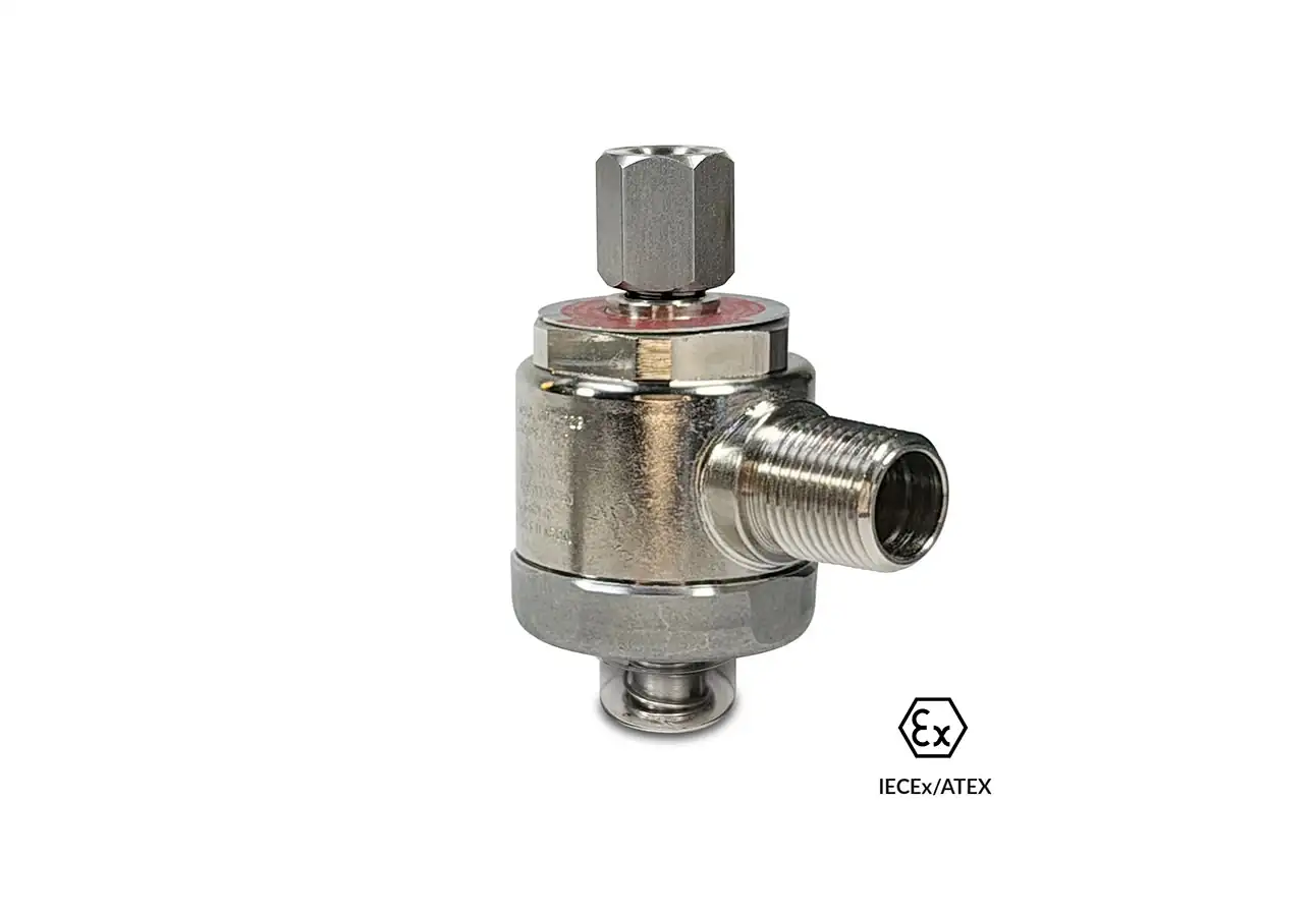
Series E20 Model EL25

Series E20 Model EL25
Series E20 Model EL25 Male Connector
Series E20 Model EL25 solenoid operator
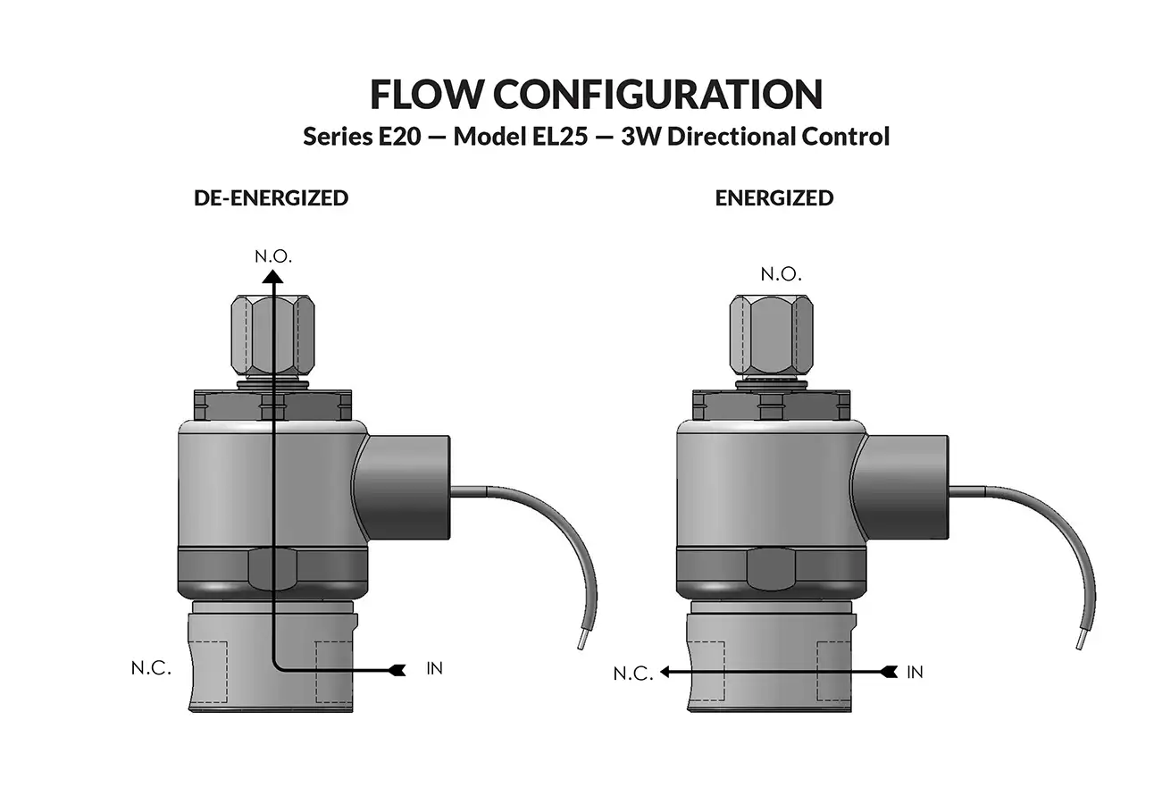
Series E20 Model EL25 flow diagram

PeterPaul explosion proof solenoid valves are used where fire or explosion hazards exist due to the presence of flammable gas or vapors, flammable liquids, combustible dust, or easily ignitable fibers. The low watt feature assures low power consumption, reducing drain on electrical systems. This is a benefit for renewable energy applications and where the solenoid valve must be on continuously.

  • Heavy duty and made of stainless steel.
  • A real workhorse with proven performance.
  • Low power consumption best for renewable energy and limited resource applications.
  • Wide range of orifice sizes from 1/32″ to 1/8″.
Valve specifications — Series 20 Model EL25
MAX. OPER. PRESS. DIFF.ORIFICE SIZECV FACTORNORTH AMERICAN
VALVE NUMBER
IECEx/ATEX
VALVE NUMBER
DCINEXHINEXH1/8 NPT PORTS1/4 NPT PORTS1/8 NPT PORTS1/4 NPT PORTS
3501/321/32.024.024EL25GG7XCCP-∆EL25GG9ZCCP-∆ELA25GG7XCCP-∆ELA25GG9ZCCP-∆
1753/643/64.052.052EL25HH7XCCP-∆EL25HH9ZCCP-∆ELA25HH7XCCP-∆ELA25HH9ZCCP-∆
1001/161/16.095.095EL25JJ7XCCP-∆EL25JJ9ZCCP-∆ELA25JJ7XCCP-∆ELA25JJ9ZCCP-∆
503/323/32.156.156EL25KK7XCCP-∆EL25KK9ZCCP-∆ELA25KK7XCCP-∆ELA25KK9ZCCP-∆

Ordering Information:

Seal Material: Replace ∆ with desired code - Blank = Nitrile (Buna) S = Low Temp Buna. N = FKM* E = Neoprene A = EPDM

When ordering valves or repair packs add voltage and frequency to complete valve number. For example: valve (EL25GG9ZCCP-N 24/DC) repair pack (2KEL25KK-N DC)

When ordering operators add the letter “O” to the front of the valve number, and the body code will change. Contact the factory for the complete part number.


Coil Voltage
12, 24/DC
Nominal Power
1.8 Watts
Coil Construction
Potted Class F coil with 36” black lead wires and 36” green ground wire.
Typical Response Time on Air
4 – 16 Milliseconds
Operating Speed
Up to 600 CPM
Duty Cycle
Continuous
Internal Components
Stainless Steel
Elastomers
Buna, Fluorocarbon (FKM), Low Temperature Buna, EPDM or Neoprene.
Orifice Diameter
See table above.
Porting
1/8” OR 1/4” NPT
Housing
Flame-Proof construction with 1/2" NPT conduit
Listings
Valves are cULus listed for Hazardous Locations. — Class I, Div 1, Group C and D – Class II, Div 1, Group E, F, and G; Div 2 Groups A, B, C, D, E, F, and G.
Life Expectancy
Millions of cycles, depending on application, lubrication, etc.
Valve Weight
1.38 lbs
Repair Packs
See table above.
Options
Alternate Port Locations, Metering, Manual Override, Alternate Elastomers, Female DIN Style Connector Part Numbers DIN COIL (2 TERMINALS W/GROUND) #20-198 & DIN COIL (3 TERMINALS W/GROUND) #20-19102*
Media
Air, water, and other fluids are compatible with standard Buna seals. Hot water, steam, gasoline, and many oils require other seal materials. (Series 20 pressure ratings may change due to the viscosity of the liquid.)*
Valve Temperature Range
-22°F(-30°C) to 140°F (60°C) Exception: FKM is -4°F (-20°C) to 140°F (60°C).
Maximum Operating Pressure Differentials
See table above.
Burst Pressure
5,000 PSI
Leakage
Bubble tight for standard valves.
Vacuum
To 5 Microns*

Series 20 HAZARDOUS LOCATION VALVES

Technical drawing — MODEL EL25 1/4-18 NPT 3-WAY DIRECTIONAL CONTROL EXPLOSION PROOF
MODEL EL25
1/4-18 NPT
3-WAY DIRECTIONAL CONTROL EXPLOSION PROOF
Technical drawing — MODEL EL25 1/8-27 NPT 3-WAY DIRECTIONAL CONTROL EXPLOSION PROOF
MODEL EL25
1/8-27 NPT
3-WAY DIRECTIONAL CONTROL EXPLOSION PROOF
Technical drawing — MODEL EL25 BODY OPTION "O" 3-WAY DIRECTIONAL CONTROL EXPLOSION PROOF
MODEL EL25
BODY OPTION "O"
3-WAY DIRECTIONAL CONTROL EXPLOSION PROOF
Technical drawing — MODEL EL25 MANUAL OVERRIDE 3-WAY DIRECTIONAL CONTROL EXPLOSION PROOF
MODEL EL25
MANUAL OVERRIDE
3-WAY DIRECTIONAL CONTROL EXPLOSION PROOF
Technical drawing — MODEL EL25 METERING 3-WAY DIRECTIONAL CONTROL EXPLOSION PROOF
MODEL EL25
METERING
3-WAY DIRECTIONAL CONTROL EXPLOSION PROOF
Minimum quantity required. Please contact sales for additional assistance.
sales@peterpaul.com
Stainless Steel (Std.)
Certification
North American
IECEx/ATEX
IECEx/ATEX Nomenclature

Coming soon.

Series E20 Model EL23 - Piped Exhaust

Series E20 Model EL23 - Piped Exhaust
Series E20 Model EL23 - Piped Exhaust Male Connector
Series E20 Model EL23 - Piped Exhaust solenoid operator
Series E20 Model EL23 - Piped Exhaust flow diagram

PeterPaul explosion-proof solenoid valves are used where fire or explosion hazards exist due to the presence of flammable gas or vapors, flammable liquids, combustible dust, or easily ignitable fibers. The low-watt feature assures low power consumption, reducing drain on electrical systems. This is a benefit for renewable energy applications and where the solenoid valve must be on continuously.

  • Heavy-duty and made of stainless steel.
  • A real workhorse with proven performance.
  • Low power consumption — best for renewable energy and limited-resource applications.
  • Wide range of orifice sizes, from 1/32″ to 1/8″.
Valve specifications — Series 20 Model EL23 - Piped Exhaust
MAX. OPER. PRESS. DIFF.ORIFICE SIZECV FACTORNORTH AMERICAN
VALVE NUMBER
IECEx/ATEX
VALVE NUMBER
DCINLETEXHINLETEXH1/8 NPT PORTS1/4 NPT PORTS1/8 NPT PORTS1/4 NPT PORTS
*3751/321/32.024.024EL23GG7XCCP-∆EL23GG9ZCCP-∆ELA23GG7XCCP-∆ELA23GG9ZCCP-∆
1503/643/64.052.052EL23HH7XCCP-∆EL23HH9ZCCP-∆ELA23HH7XCCP-∆ELA23HH9ZCCP-∆
1503/641/16.052.095EL23HJ7XCCP-∆EL23HJ9ZCCP-∆ELA23HJ7XCCP-∆ELA23HJ9ZCCP-∆
1001/161/16.095.095EL23JJ7XCCP-∆EL23JJ9ZCCP-∆ELA23JJ7XCCP-∆ELA23JJ9ZCCP-∆
1001/163/32.095.156EL23JK7XCCP-∆EL23JK9ZCCP-∆ELA23JK7XCCP-∆ELA23JK9ZCCP-∆
503/323/32.284.156EL23KK7XCCP-∆EL23KK9ZCCP-∆ELA23KK7XCCP-∆ELA23KK9ZCCP-∆
351/83/32.284.156EL23NK7XCCP-∆EL23NK9ZCCP-∆ELA23NK7XCCP-∆ELA23NK9ZCCP-∆
201/81/8.284.201EL23NN7XCCP-∆EL23NN9ZCCP-∆ELA23NN7XCCP-∆ELA23NN9ZCCP-∆

Ordering Information:

* Rating may vary based on an elastomer choice.

Seal Material: Replace ∆ with desired code - Blank = Nitrile (Buna) S = Low Temp Buna. N = FKM* E = Neoprene A = EPDM

When ordering valves or repair packs add voltage and frequency to complete valve number. For example: valve (EL23JJ7XCCP-N 24/DC) repair pack (2KEL23JJ-N DC)

When ordering operators add the letter “O” to the front of the valve number, and the body code will change. Contact the factory for the complete part number.


Coil Voltage
12, 24/DC
Nominal Power
1.8 Watts
Coil Construction
Potted Class F coil with 36” black lead wires and 36” green ground wire.
Typical Response Time on Air
4 – 16 Milliseconds
Operating Speed
Up to 600 CPM
Duty Cycle
Continuous
Internal Components
Stainless Steel
Elastomers
Buna, Fluorocarbon (FKM), Low Temperature Buna, EPDM or Neoprene.
Orifice Diameter
See table above.
Porting
1/8” OR 1/4” NPT
Housing
Flame-Proof construction with 1/2" NPT conduit
Listings
Valves are cULus listed for Hazardous Locations. — Class I, Div 1, Group C and D – Class II, Div 1, Group E, F, and G; Div 2 Groups A, B, C, D, E, F, and G.
Life Expectancy
Millions of cycles, depending on application, lubrication, etc.
Valve Weight
1.38 lbs
Repair Packs
See table above.
Options
Alternate Port Locations, Metering, Manual Override, Alternate Elastomers, Female DIN Style Connector Part Numbers DIN COIL (2 TERMINALS W/GROUND) #20-198 & DIN COIL (3 TERMINALS W/GROUND) #20-19102*
Media
Air, water, and other fluids are compatible with standard Buna seals. Hot water, steam, gasoline, and many oils require other seal materials. (Series 20 pressure ratings may change due to the viscosity of the liquid.)*
Valve Temperature Range
-22°F(-30°C) to 140°F (60°C) Exception: FKM is -4°F (-20°C) to 140°F (60°C).
Maximum Operating Pressure Differentials
See table above.
Burst Pressure
5,000 PSI
Leakage
Bubble tight for standard valves.
Vacuum
To 5 Microns*

Series 20 HAZARDOUS LOCATION VALVES

Technical drawing — MODEL EL23 1/4-18 NPT 3WNC PIPED EXHAUST EXPLOSION PROOF
MODEL EL23
1/4-18 NPT
3WNC PIPED EXHAUST EXPLOSION PROOF
Technical drawing — MODEL EL23 1/8-27 NPT 3WNC PIPED EXHAUST EXPLOSION PROOF
MODEL EL23
1/8-27 NPT
3WNC PIPED EXHAUST EXPLOSION PROOF
Technical drawing — MODEL EL23 BODY OPTION "O" 3WNC PIPED EXHAUST EXPLOSION PROOF
MODEL EL23
BODY OPTION "O"
3WNC PIPED EXHAUST EXPLOSION PROOF
Technical drawing — MODEL EL23 MANUAL OVERRIDE 3WNC PIPED EXHAUST EXPLOSION PROOF
MODEL EL23
MANUAL OVERRIDE
3WNC PIPED EXHAUST EXPLOSION PROOF
Technical drawing — MODEL EL23 METERING 3WNC PIPED EXHAUST EXPLOSION PROOF
MODEL EL23
METERING
3WNC PIPED EXHAUST EXPLOSION PROOF
Minimum quantity required. Please contact sales for additional assistance.
sales@peterpaul.com
 
Stainless Steel (Std.)
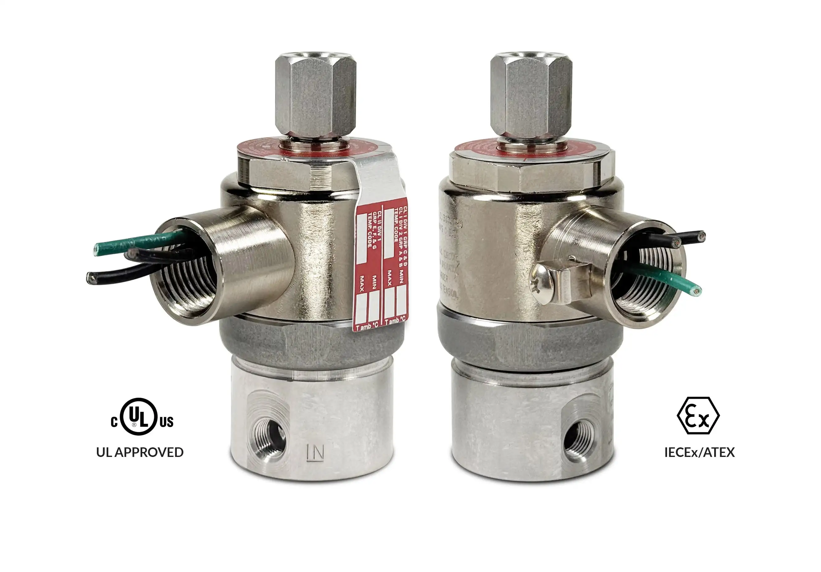
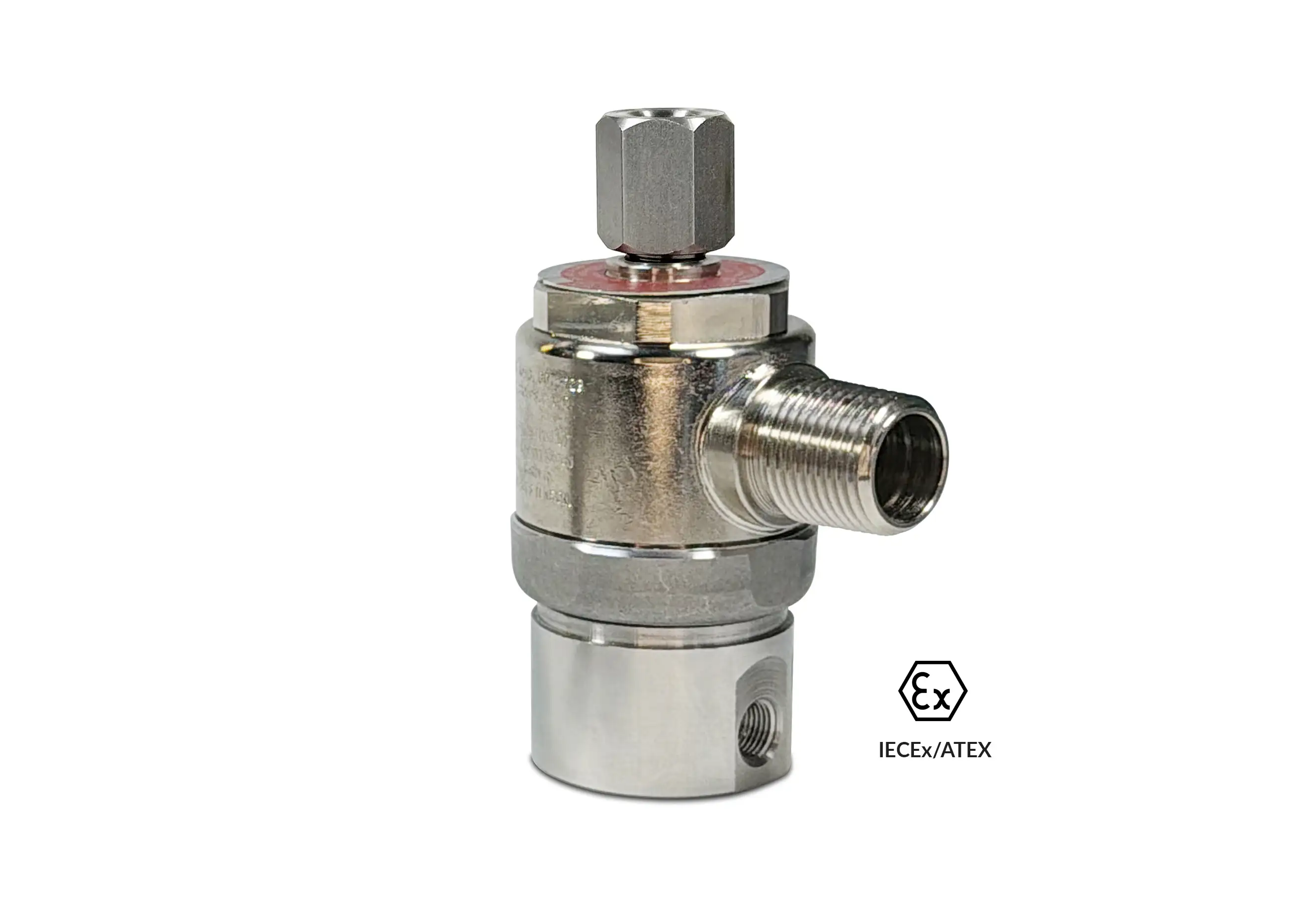
Certification
North American
IECEx/ATEX
IECEx/ATEX Nomenclature

Coming soon.

Series 20 Model MLVH22 (REVERSE POLARITY)

Series 20 Model MLVH22 (REVERSE POLARITY)
Series 20 Model MLVH22 (REVERSE POLARITY) solenoid operator
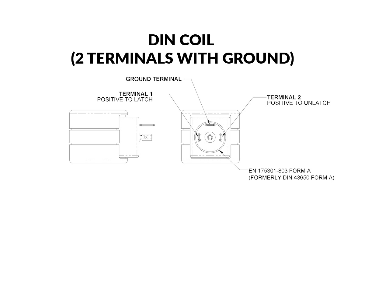
DIN coil (2 terminals with ground) wiring diagram
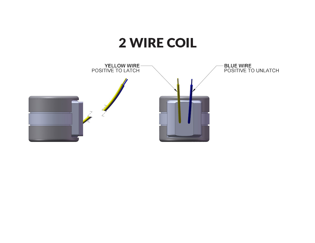
2 wire coil wiring diagram
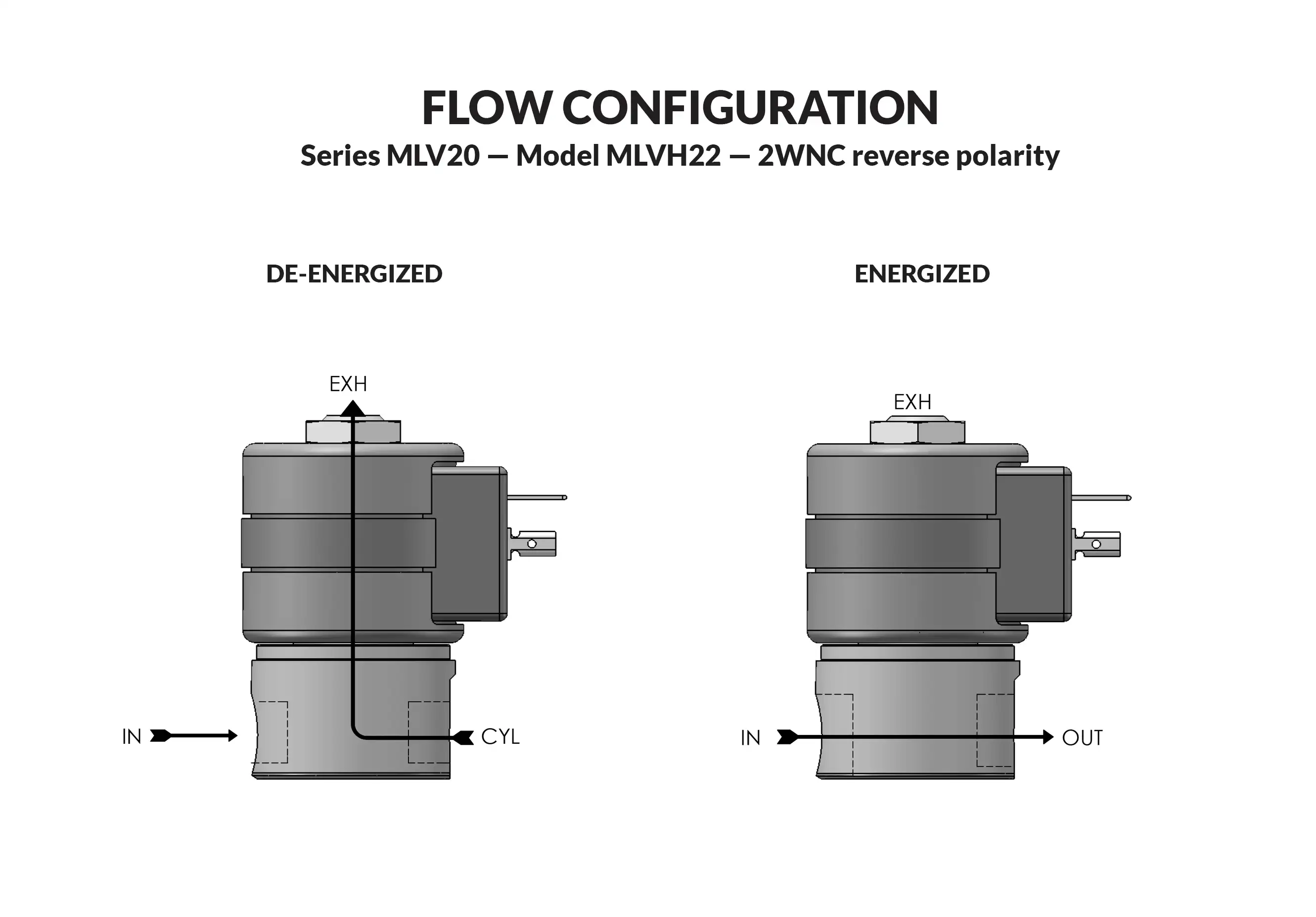
Series 20 Model MLVH22 (REVERSE POLARITY) flow diagram

2-Way Reverse Polarity Magnetic Latching Valve - When the coil is energized, the plunger accelerates toward the sleeve end stop and strikes the sealing pin, transferring force to lift the pin from the seat. A return spring acts directly on the pin to reseal the orifice when energized with reverse polarity. Suitable for air and other non-corrosive gases, water, and oil.

  • Kel-F pin sealing element.
  • Orifice guides the sealing pin for precise alignment.
  • Simple construction with only two moving parts.
  • A permanent magnet makes the valve bi-stable in either shifted state, allowing it to remain latched indefinitely without drawing power. A short 50 millisecond DC pulse shifts the valve, while a reverse-polarity pulse shifts it back. This makes the valve ideal for remote applications where continuous power is limited and for equipment where coil heating is undesirable, including medical and chemical analyzers.

Neutral (−) a. Pulse Yellow lead to Positive (+) to latch   b. Pulse Blue lead to Positive (+) to un-latch  

Positive (+) a. Pulse Yellow lead to Neutral (−) to un-latch   b. Pulse Blue lead to Neutral (−) to latch  

Valve specifications — Series 20 Model MLVH22 (REVERSE POLARITY)
GAS PRESSURE RATINGSORIFICE SIZECV FACTORVALVE NUMBER DIN COIL
(2 TERMINALS WITH GROUND)
VALVE NUMBER
2 WIRE COIL
DC1/8 NPT PORTS1/4 NPT PORTS1/8 NPT PORTS1/4 NPT PORTS
3300*.025.010H22M7DELM-∆H22M9DELM-∆H22M7DGLM-∆H22M9DGLM-∆
1400*1/32.022H22G7DELM-∆H22G9DELM-∆H22G7DGLM-∆H22G9DGLM-∆
1050*3/64.041H22H7DELM-∆H22H9DELM-∆H22H7DGLM-∆H22H9DGLM-∆
4251/16.065H22J7DELM-∆H22J9DELM-∆H22J7DGLM-∆H22J9DGLM-∆
1503/32.100H22K7DELM-∆H22K9DELM-∆H22K7DGLM-∆H22K9DGLM-∆

* FKM seals not recommended for pressures of 500 psi and above.

Ordering Information:

Seal Material: Replace ∆ with desired code - Blank = Nitrile (Buna) S = Low Temp Buna. N = FKM* E = Neoprene A = EPDM

When ordering valves or repair packs add voltage and frequency to complete valve number. For example: valve (H22J7DELM-∆ 24/DC) repair pack (KH22JD LM)


Coil Voltage
6, 9, 12, 24/DC
Nominal Power
10 Watts
Coil Construction
Molded (Std.), Non-molded Class A and Potted Class F or Class H (Opt.)
Typical Response Time on Air
4 - 16 Milliseconds
Operating Speed
Up to 600 CPM with gas media
Duty Cycle
Continuous
Internal Components
Stainless Steel.
Elastomers
Nitrile (Buna) (Std.). Many other elastomers available.*
Sealing Pin
Kel-F (Std.)
Orifice Diameter
See table above.
Porting
1/8" and 1/4" NPT (other ports available).
Housing
Grommet and 1/2" NPT conduit – many options available.*
Mounting
Must be mounted within 30° of vertical.
Life Expectancy
Millions of cycles, depending on application, lubrication, etc.
Valve Weight
1.13 lbs
Repair Packs
See table above.
Options
Alternate Port Locations, Metering and Alternate Elastomers, Female DIN Style Connector Part Numbers DIN COIL (2 TERMINALS W/GROUND) #20-198 & DIN COIL (3 TERMINALS W/GROUND) #20-19102. Consult representative or factory for more options & specifications.
Media
Air and other non-corrosive gasses, water and oil.
Valve Temperature Range
Standard Valves – 0°F (-18°C) to 104°F (40°C) ambient; 0°F (-18°C) to 150°F (65°C) media. Optional Valves – can tolerate much higher or much lower ambient and media temperatures.*
Maximum Operating Pressure Differentials
See table above.
Burst Pressure
10,000 PSI
Leakage
Bubbletight (with polymer sealing pins)

Series 20 High Pressure Valves DIN

Technical drawing — MODEL H22 1/4-18 NPT 2WNC DIN STYLE COIL
MODEL H22
1/4-18 NPT
2WNC DIN STYLE COIL

Technical drawing — MODEL H22 1/8-27 NPT 2WNC DIN STYLE COIL
MODEL H22
1/8-27 NPT
2WNC DIN STYLE COIL

Technical drawing — MODEL H22 STUD MOUNT 2WNC DIN STYLE COIL
MODEL H22
STUD MOUNT
2WNC DIN STYLE COIL


Series 20 High Pressure Valves Grommet

Technical drawing — MODEL H22 1/4-18 NPT 2WNC GROMMET WITH LEADS
MODEL H22
1/4-18 NPT
2WNC GROMMET WITH LEADS

Technical drawing — MODEL H22 1/8-27 NPT 2WNC GROMMET WITH LEADS
MODEL H22
1/8-27 NPT
2WNC GROMMET WITH LEADS

Technical drawing — MODEL H22 STUD MOUNT 2WNC GROMMET WITH LEADS
MODEL H22
STUD MOUNT
2WNC GROMMET WITH LEADS


Stainless Steel (Std.)

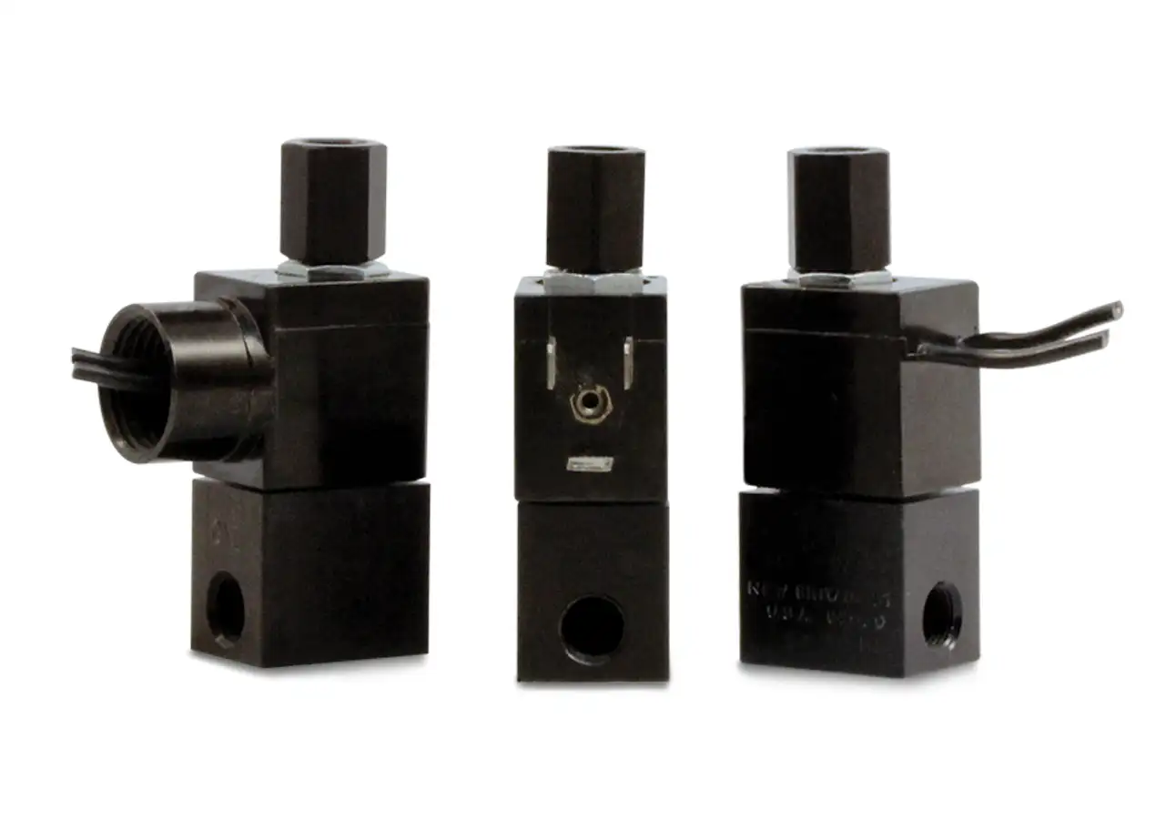
Series 15 Model 151

Series 15 Model 151
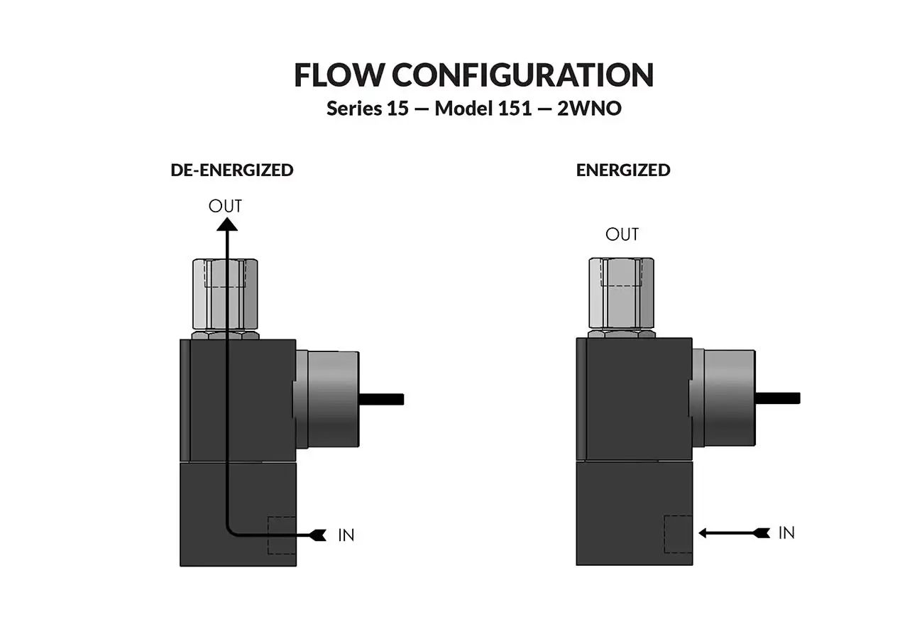
Series 15 Model 151 flow diagram

The little black box — magnetic components encased in epoxy for durability and reliability. Interior parts are stainless steel and anodized aluminum. The valves may be used with air, inert gas and liquid media at pressures from vacuum to 400 psi — depending upon orifice size and configuration. For those who require extra heat resistance and media compatibility, FKM and other elastomers are available.

  • Small, lightweight and economical.
  • Operating pressures from vacuum to 400 psi.
  • Quality design and construction.
Valve specifications — Series 15 Model 151
MAX. OPER.
PRESS. DIFF.
ORIFICE SIZECV FACTORVALVE NUMBER
LEAD WIRE
VALVE NUMBER
DIN STYLE
VALVE NUMBER
CONDUIT HOUSING
ACDC
4004001/32.020151G2XGM151G2XEM151G2XCM
2002003/64.048151H2XGM151H2XEM151H2XCM
1251251/16.075151J2XGM151J2XEM151J2XCM
40403/32.130151K2XGM151K2XEM151K2XCM

Ordering Information:

When ordering valves or repair packs add voltage and frequency to complete valve number. For example: valve (151J2XGM 120/60) repair pack (K151JX AC)

When ordering operators add the letter “O” to the front of the valve number, replace body port number with the letter “D”: example: operator (O151JDXGM 120/60)


Coil Voltage
12/DC, 24/DC, 48/DC, 125/DC, 120/60-110/50, 240/60, and 24/60.
Nominal Power
AC — 8.5 Watts, DC — 10.5 Watts
Coil Construction
Molded Class F. (155°C)
Typical Response Time on Air
4 - 16 Milliseconds
Operating Speed
Up to 600 CPM
Duty Cycle
Continuous
Internal Components
Stainless Steel. Copper – AC Only.
Elastomers
Nitrile (Buna) (Std.). Many other elastomers available.*
Orifice Diameter
See table above.
Porting
1/8" NPT (Std.)
Housing
Leadwires, 1/2” NPT Conduit and DIN Style Connector.
Listings
Most valves are UL and CSA listed.*
Life Expectancy
Millions of cycles, depending on application, lubrication, etc.
Valve Weight
0.27 lb to 0.30 lb depending on model and housing style.
Repair Packs
See table above.
Options
Round Brass or Stainless Steel Body, Stackable Construction, Alternate Elastomers and Magnetic Latching Coil. Female DIN Style Connector Part Number 50-17029 *
Media
Air, water, and other fluids compatible with standard Buna seals. Hot water, steam, gasoline, and many oils require special seal materials. (Series 15 pressure ratings may change due to the viscosity of the liquid.)*
Valve Temperature Range
Standard Valves – 0°F (-18°C) to 104°F (40°C) ambient; 0°F (-18°C) to 150°F (65°C) media. Optional Valves – can tolerate much higher or much lower ambient and media temperatures.*
Maximum Operating Pressure Differentials
See table above.
Burst Pressure
5,000 PSI
Leakage
Bubble tight for standard valves.
Vacuum
To 5 Microns*

Series 15 General Purpose Valves

Technical drawing — MODEL 151 2WNO CONDUIT CONNECTION ALUMINUM BODY WITH 1/8-27 NPT PORTS
MODEL 151 2WNO CONDUIT CONNECTION ALUMINUM BODY WITH 1/8-27 NPT PORTS
Technical drawing — MODEL 151 2WNO DIN STYLE COIL ALUMINUM BODY WITH 1/8-27 NPT PORTS
MODEL 151 2WNO DIN STYLE COIL ALUMINUM BODY WITH 1/8-27 NPT PORTS
Technical drawing — MODEL 151 2WNO MOLDED COIL WITH LEADS ALUMINUM BODY WITH 1/8-27 NPT PORTS
MODEL 151 2WNO MOLDED COIL WITH LEADS ALUMINUM BODY WITH 1/8-27 NPT PORTS
Anodized Aluminum (Std.)

Series 15 Operators Conduit

Technical drawing — MODEL O151 2WNO CONDUIT CONNECTION
MODEL O151 2WNO CONDUIT CONNECTION

Series 15 Operators DIN

Technical drawing — MODEL O151 2WNO DIN STYLE COIL
MODEL O151 2WNO DIN STYLE COIL

Series 15 Operators Molded Leads

Technical drawing — MODEL O151 2WNO MOLDED COIL WITH LEADS
MODEL O151 2WNO MOLDED COIL WITH LEADS

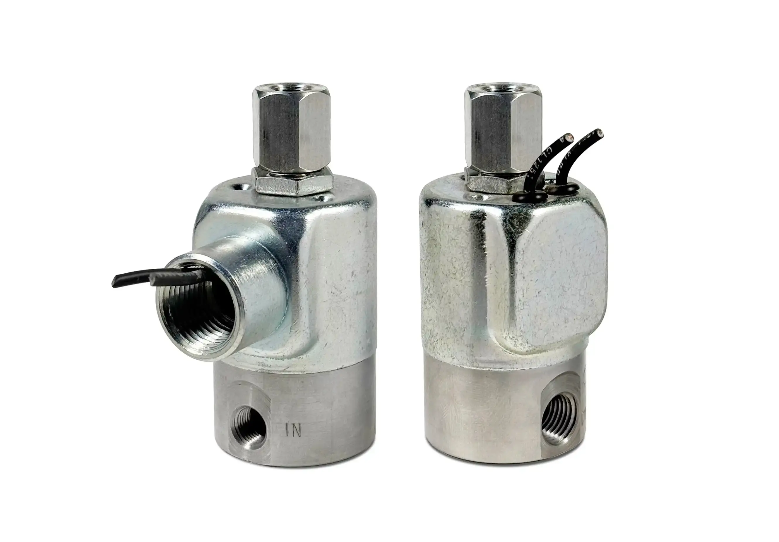
Series 20 Model H21

Series 20 Model H21
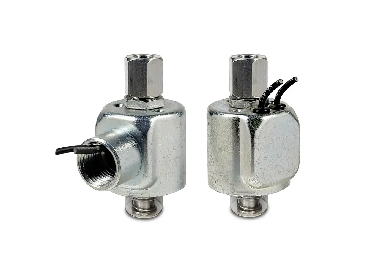
Series 20 Model H21 solenoid operator
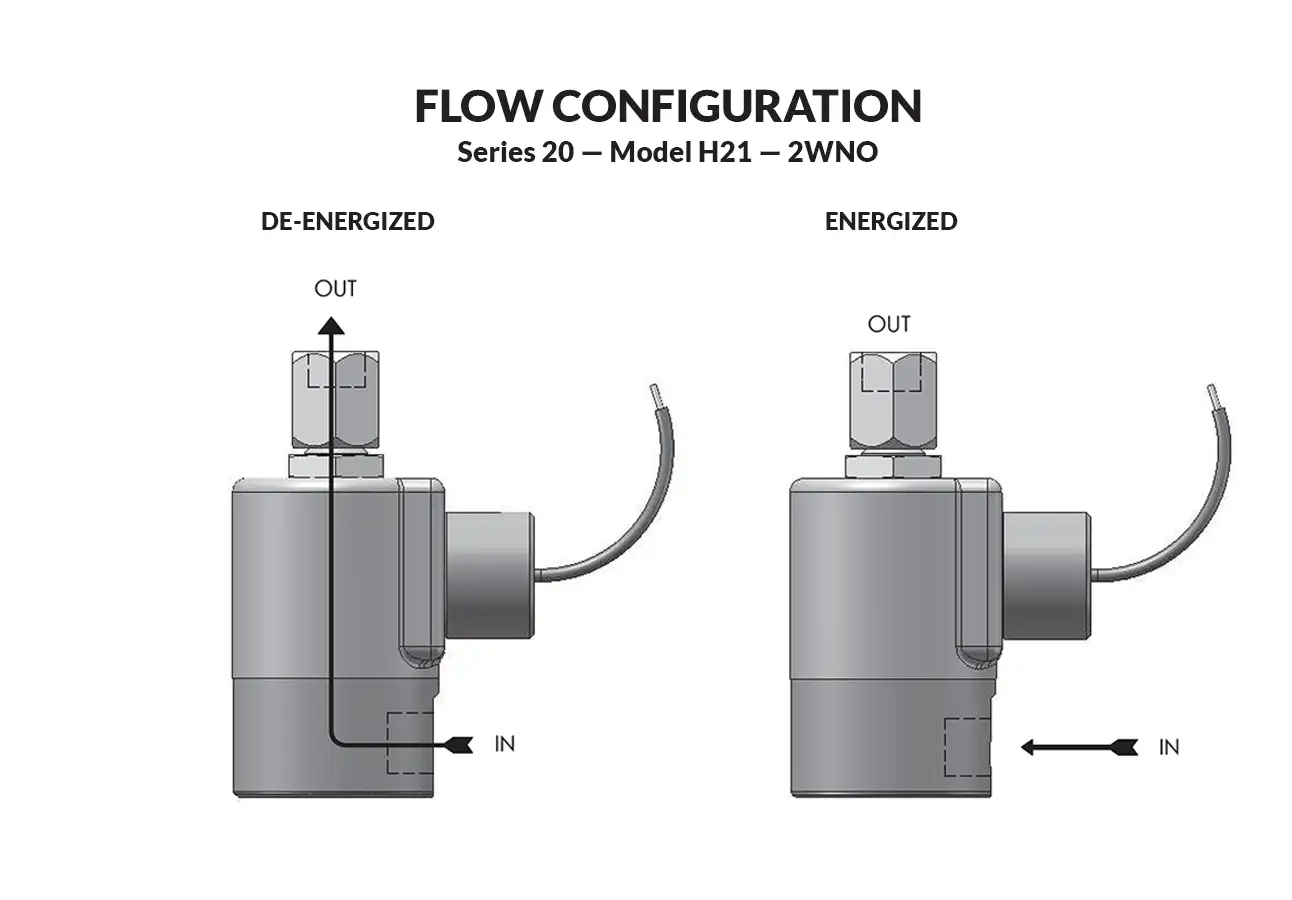
Series 20 Model H21 flow diagram

This valve uses a pin style seal. The pin is guided into the orifice. For use on air and other non-corrosive gases, water and oil.
  • Kel-F pin sealing element.
  • Orifice guides the sealing pin for perfect alignment.
  • Simple construction...only three moving parts.
Valve specifications — Series 20 Model H21
MAX. OPER. PRESS. DIFF.ORIFICE SIZE
CV FACTOR
VALVE NUMBER
GROMMET HOUSING
VALVE NUMBER
CONDUIT HOUSING
DC1/8" NPT PORTS1/4" NPT PORTS1/8" NPT PORTS1/4" NPT PORTS
2000*.6mm.010H21M7XGMH21M9ZGMH21M7XCMH21M9ZCM

* FKM seals not recommended for pressure above 500 psi.

Ordering Information:

When ordering valves or repair packs add voltage and frequency to complete valve number. For example: valve (H21M7XGV 12/DC) repair pack (KH21MX DC)

When ordering operators add the letter “O” to the front of the valve number, replace body port number with the letter “D”: example: operator (OH21MDXGV 12/DC)


Coil Voltage
12, 24/DC
Nominal Power
DC — 9.5 Watts
Coil Construction
Molded (Std.), Non-molded Class A and Potted Class F or Class H (Opt.)
Typical Response Time on Air
4 - 16 Milliseconds
Operating Speed
Up to 600 CPM with gas media
Duty Cycle
Continuous
Internal Components
Stainless Steel
Elastomers
Nitrile (Buna) (Std.). Many other elastomers available.*
Sealing Pin
Kel-F (Std.), Delrin®, PEEK
Orifice Diameter
See table above.
Porting
1/8" NPT and 1/4" NPT (other ports available).
Housing
Grommet and 1/2" NPT conduit
Life Expectancy
Millions of cycles, depending on application, lubrication, etc.
Valve Weight
1.19 lbs
Repair Packs
See table above.
Options
Alternate Elastomers, Alternate Sealing Pin Materials, Spade Terminal Coil, and European Style DIN, Female DIN Style Connector Part Numbers DIN COIL (2 TERMINALS W/GROUND) #20-198 & DIN COIL (3 TERMINALS W/GROUND) #20-19102*
Media
Air and other non-corrosive gasses, water and oil.
Valve Temperature Range
Standard Valves – 0°F (-18°C) to 104°F (40°C) ambient; 0°F (-18°C) to 150°F (65°C) media. Optional Valves – can tolerate much higher or much lower ambient and media temperatures.*
Maximum Operating Pressure Differentials
See table above.
Burst Pressure
10,000 PSI
Leakage
Bubble tight

Series 20 High Pressure Valves Conduit Connection

Technical drawing — MODEL H21 1/4 NPT 2WNO HIGH PRESSURE CONDUIT CONNECTION
MODEL H21
1/4 NPT
2WNO HIGH PRESSURE CONDUIT CONNECTION
Technical drawing — MODEL H21 1/8 NPT 2WNO HIGH PRESSURE CONDUIT CONNECTION
MODEL H21
1/8 NPT
2WNO HIGH PRESSURE CONDUIT CONNECTION
 

Series 20 High Pressure Valves DIN Connection

Technical drawing — MODEL H21 1/4 NPT 2WNO HIGH PRESSURE DIN STYLE COIL
MODEL H21
1/4 NPT
2WNO HIGH PRESSURE DIN STYLE COIL
Technical drawing — MODEL H21 1/8 NPT 2WNO HIGH PRESSURE DIN STYLE COIL
MODEL H21
1/8 NPT
2WNO HIGH PRESSURE DIN STYLE COIL
 

Series 20 High Pressure Valves Grommet Connection

Technical drawing — MODEL H21 1/4 NPT 2WNO HIGH PRESSURE GROMMET STYLE COIL
MODEL H21
1/4 NPT
2WNO HIGH PRESSURE GROMMET STYLE COIL
Technical drawing — MODEL H21 1/8 NPT 2WNO HIGH PRESSURE GROMMET STYLE COIL
MODEL H21
1/8 NPT
2WNO HIGH PRESSURE GROMMET STYLE COIL
 

Series 20 High Pressure Valves Yoke Leads

Technical drawing — MODEL H21 1/4 NPT 2WNO HIGH PRESSURE YOKE WITH LEADS
MODEL H21
1/4 NPT
2WNO HIGH PRESSURE YOKE WITH LEADS
Technical drawing — MODEL H21 1/8 NPT 2WNO HIGH PRESSURE YOKE WITH LEADS
MODEL H21
1/8 NPT
2WNO HIGH PRESSURE YOKE WITH LEADS
 

Series 20 High Pressure Valves Yoke Spades

Technical drawing — MODEL H21 1/4 NPT 2WNO HIGH PRESSURE YOKE WITH SPADE TERMINALS
MODEL H21
1/4 NPT
2WNO HIGH PRESSURE YOKE WITH SPADE TERMINALS
Technical drawing — MODEL H21 1/8 NPT 2WNO HIGH PRESSURE YOKE WITH SPADE TERMINALS
MODEL H21
1/8 NPT
2WNO HIGH PRESSURE YOKE WITH SPADE TERMINALS
 
Stainless Steel
We will be closed

PeterPaul will be closed Monday, October 12th. We will re-open Tuesday, October 13th for regular business hours.  Please feel free to email us using the chat box below.